How to configure transformer capacity, ten years old electrician tell you these rules!
In AC circuit, there are three concepts of electric power: active power, reactive power and apparent power. KVA stands for apparent power, which includes reactive power and active power. KW stands for active power, and kVar stands for reactive power. The relation between kW and kVar and conversion there is a concept - power factor cos ф, active power kW=UIcos ф, reactive power kVar=UIsin ф, and apparent power kVA=UI(U is voltage, I is current).
 Audited supplier
When applying to the power supply bureau, you should fill in the active power you need to use, that is, how many kW is needed. If the total power consumption of the building is calculated to be 4500kW, for such a large amount, the power board will definitely require reactive power compensation. Assume that your compensated power factor is above 0.9. The apparent power will need 4500÷0.9=5000kVA, and then consider a certain load margin and transformer specifications, I'm afraid the minimum 5600kVA transformer. Of course, this is just calculation, in actual use, still have to see your load at the same time rate and other factors to consider.
About transformer capacity selection, there are the following rules for reference!
Given the transformer capacity, find its voltage grade side rated current
Description: Suitable for any voltage level.
Formula: capacity divided by voltage, multiplied by six divided by ten.
Case study:
Apparent current I= apparent power S/1.732 * 10KV=1000KVA/1.732 * 10KV=57.736A
Estimated I=1000KVA/10KV * 6/10=60A

Known transformer capacity, quick calculation of primary and secondary protection fuses current value
Transformer high voltage fuse, capacity voltage comparison.
With variable low voltage fuse, capacity multiplied by 9 divided by 5
Measure the secondary current of the power transformer and calculate its load capacity
Known distribution variable secondary voltage, measured current kilowatts.
Voltage class 400 volts, one ampere 0.6 kilowatts.
Voltage rating 3,000 volts, 1 amp 4.5 kilowatts.
Voltage class 6,000 volts, one amp integer nine kilowatts.
Voltage class 10 kv, 1 amp 15 kW.
Voltage level 35,000, 1 amp 55 kilowatts.
4. Given the transformer capacity, find the rated current of its voltage grade side
Common voltage coefficient, capacitive multiplication coefficient of the current,
Rated at 400 volts, coefficient 1.44,
Rated voltage 6000 volts, coefficient zero 096,
Rated at 10,000 volts, coefficient is just 0.6.
Note: the rated current of the voltage grade side can be obtained by multiplying the transformer capacity directly by the corresponding coefficient.
Select the melt current value of primary and secondary fuses according to the rated capacity and voltage of transformer
The melt flow on both sides of the distribution is calculated simply according to the capacity,
The unit of capacity is kilovolt ampere and the unit of voltage is kilovolt.
High voltage capacity divided by voltage, low voltage multiplied by 1.8,
The unit of current ampere is obtained, and then subtracted or added by grade.
Case study:
The rated capacity of the three-phase power transformer is 315KVA, the rated voltage of the high end is 6KV, and the rated voltage of the low end is 400V;
The rated current of the melt at the high pressure side is (315÷6) A= 52.5a; The rated current of the low-voltage side melt is (315×1.8) A=567A
Note: the choice of fuse specification shall be determined by the difference between the calculated value and the melt current gauge.
Select the melt current value of primary and secondary fuses according to the rated current of the transformer
With the melt flow on both sides of the transformer, calculate the rated current several times,
The value of high pressure side is larger, and the number varies with different capacity.
Capacity up to 100, two to three times the amount of current,
If it's over a hundred, it's reduced by two to one and a half,
The minimum high voltage is specified and cannot be less than three amps.
Low pressure is equal to the rated value regardless of the volume value.
7 Installation requirements for power distribution transformers
At least two and a half meters from the ground, with barriers installed on the ground,
The barrier is at least 1.8 meters high, leaving the match point eight,
If the economy permits, it is more appropriate to use the box type.
Should not be placed in the open unless temporarily used.
Indoor installation should be ventilated, and the surrounding channels should be appropriate.
8 Supply voltage quality for distribution transformers
Only when the supply voltage is guaranteed, can the equipment run normally
The high and low deviation is specified. The voltage is different.
The voltage between lines is plus or minus seven, minus ten plus seven is phase,
If the requirements are more special, the supply and demand parties to discuss.
Resolution:
In China's low-voltage power supply system, the line voltage is 380V, and the allowable deviation is ± 7%, that is 353.4 ~ 406.6V; The phase voltage is 220V, and the allowable deviation is -10% ~ + 7%, i.e. 198 ~ 235.4V.
Transformer insulation winding detection
Ensure safe operation of transformation and check hidden dangers by measuring insulation.
Use megohm meter to measure, select meter according to voltage.
More than three, five, two, five, and a thousand under ten.
The E end of the instrument should be connected to the ground, and the G end should be added for serious pollution.
Unmeasured winding and components, reliable grounding to ensure safety.
Hand rotation speed 120, after the test discharge and then remove the wire.
Note: for 35KV and above transformers should use 2500V megohmmeter; For transformers up to and including 10KV, 1000V megohmmeter should be used, L end connected to the winding of the transformer, E end grounded.
Parallel operation of two transformers
Parallel two transformers, four conditions to prepare;
Wiring groups should be the same, there should be the same transformer ratio;
Impedance voltage should be consistent, connected with each other in phase sequence;
The capacity difference should not be much, it is best not to exceed three to one.
11 The fuse of the distribution transformer is broken
If the high pressure fuse is broken, six reasons to judge.
The fuse specification is small; Poor quality damage difficult to bear;
High voltage lead short circuit; Internal insulation breakdown;
Damage by lightning impact; Casing rupture or breakdown.
If the low pressure fuse is broken, five reasons to judge.
The fuse specification is small; Poor quality damage difficult to bear;
Excessive load for a long time; Winding insulation breakdown;
Transmission line failure, short or alternate with ground.
Measure the no-load current of 380V single-phase welding transformer without nameplate and calculate its rated capacity
Formula: 380 welder capacity, no load current times five.
Resolution:
Single-phase AC welding transformer is actually a special purpose step-down transformer. Compared with ordinary transformer, its basic working principle is roughly the same. In order to meet the requirements of welding process, the welding transformer works under the condition of short circuit, and it is required to have a certain arc starting voltage during welding.
When the welding current increases, the output voltage decreases sharply. According to P=UI (constant power, voltage is inversely proportional to current). When the voltage falls to zero (that is, the secondary side short circuit), the secondary side current is not too large and so on, that is, the welding transformer has the external characteristics of steep drop, the external characteristics of the welding transformer is obtained by the voltage drop generated by the reactance coil.
No load, because there is no welding current through, reactance coil does not produce voltage drop, at this time the no-load voltage is equal to the secondary voltage, that is to say, the welding transformer no-load and ordinary transformer no-load the same. The no-load current of the transformer is generally about 6%~8% of the rated current (the state stipulates that the no-load current should not be greater than 10% of the rated current)
13 Know the capacity of three-phase motor, find its rated current
Formula: capacity divided by the number of kilovolts, times the coefficient point 76.
Case study:
Three phase 222 motor known, kilowatt 3.5 amperes.
1 kw present 0.22 KV * 0.76 material 1a
We have a high-voltage 3,000 volt motor, four kilowatts per ampere.
4 kw present 3 kv * 0.76 material 1a
Note: the formula is applicable to the calculation of rated current of three-phase motors of any voltage grade. When the formula is used, the capacity unit is kW, the voltage unit is kV and the current unit is A.

Audited supplier
How to judge and deal with these abnormal phenomena in transformers?
55 Transformer Knowledge You Have to Know
Transformer No-load/Load Test Introduction
What is the main power transformer factory look like
Attending the MIDDLE EAST ELECTRICITY in March
China The Main Power Transformers manufacturers - Canwin
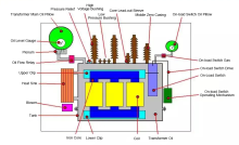
The Knowledge About Power Transformer-Oil Tank Part
The knowledge about "Power Transformer" is all here, Very Comprehensive, Collect it and Learn it!
What impact might the Russian-Ukrainian conflict have on the motor industry? Supplier