Transformer No-load/Load Test Introduction
No-load test: Apply the rated voltage of the sine wave rated frequency from a certain winding of the transformer (generally from the secondary low-voltage side), and open the other windings to measure the no-load current and no-load loss. If the test conditions are limited and the power supply voltage cannot reach the rated voltage, the test can be performed under non-rated voltage conditions. This test method has a large error and is generally only used to check whether the transformer is faulty. Only the test voltage reaches more than 80% of the rated voltage. can be used to test the no-load loss.
 Audited supplier
Short-circuit test: artificially short-circuit the low-voltage and high-current side of the transformer, and pass the test voltage of the rated frequency from the rated tap of the coil on the high-voltage side to make the current in the winding reach the rated value, and then measure the input power and the applied voltage ( i.e. short-circuit loss and short-circuit voltage) and current value. Usually the capacity of the test power supply should be 30% of the capacity of the tested product.
Zero sequence impedance: The impedance realized by a transformer to each phase sequence (positive, negative, zero) voltage and current is called sequence impedance, and they are positive sequence, negative sequence and zero sequence impedance respectively. The positive sequence impedance is actually the impedance displayed during normal operation. When the system operates asymmetrically, zero sequence current will be generated. The positive sequence impedance of the transformer is equal to the negative sequence impedance, and is equal to the short-circuit impedance of the transformer. For zero-sequence impedance, because at any instant, the magnitude and direction of zero-sequence currents of all three phases are the same, that is, their sum is not equal to zero, so zero-sequence impedance is intrinsically related to positive-sequence impedance and negative-sequence impedance. The difference is that its size is not only related to the connection method of the winding, but also to the structure of the iron core. Therefore, the zero-sequence impedance must be determined by actual measurement.
Testing Method
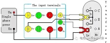
⑴ Single-phase no-load test
Single-phase no-load test items are usually used to test the no-load loss and no-load current percentage of single-phase transformers. It can also be used for phase-by-phase testing of three-phase transformers (mainly used to detect whether the transformer under test has single-phase faults). This test method is also required when there is no three-phase power supply on site.
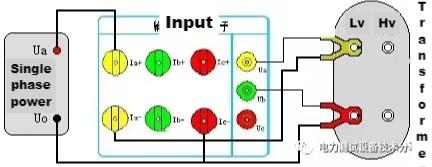
Single-phase no-load test with the A-phase voltage and A-phase current of the instrument. As shown in the figure, use a single-phase power supply as the test power supply, the live wire is connected to the positive terminal of the A-phase current terminal of the tester, the thick yellow wire is connected to the negative terminal of the A-phase current terminal, and the thin wire is connected to the A-phase voltage terminal Ua , The thick line of red pliers is directly connected to the zero line of the test power supply, the thin line is connected to the B-phase voltage terminal Ub, and the two pliers are respectively clamped to the two terminals on the low-voltage side. The high voltage side is open.
This method is also suitable for no-load loss measurement of three-phase transformers with single-phase power. When it is found that the loss exceeds the standard after the three-phase no-load test, the three-phase loss should be measured separately. Through the analysis and comparison of the no-load loss of each phase, the distribution of the no-load loss in each phase can be observed to check the winding or magnetic circuit of each phase. with or without local defects. Short-circuit one-phase winding of the transformer in turn, apply voltage to the other two-phase windings, and measure the no-load loss and no-load current. The wiring diagram is shown in the figure, according to the winding connection method of the transformer under test, the pressurization method can be divided into three situations as shown in the figure below.
a. The pressurized winding is △ connected
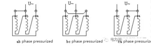
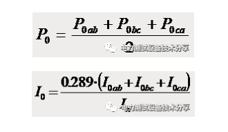
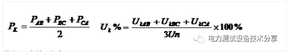
During the measurement, pressurize the ab, bc, and ca phases in turn, and short-circuit the non-pressurized windings. The measured loss is calculated according to the following formula:
Note: In the formula, In is the rated current of the test coil
b. The pressurized winding is connected to Y and has a neutral point lead out:
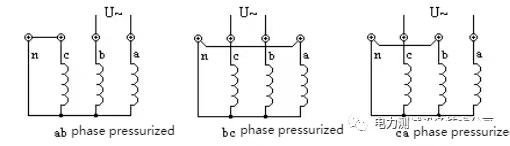
When measuring, the non-pressurized winding is short-circuited; the applied voltage is twice the phase voltage, the loss result is calculated according to formula 1, and the no-load current result is according to formula 2 (0.289 in the formula is changed to 0.333).
c. The pressurized winding is connected to Y, and there is no neutral point drawn out:
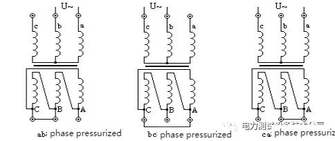
When the non-pressurized winding cannot be short-circuited because the neutral point is not drawn, the corresponding phase of the secondary winding must be short-circuited during measurement; the applied voltage should be twice the phase voltage.
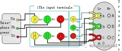
⑵ Three-phase no-load test
Wiring as shown

Use the three-phase voltage regulator as the test power supply, connect the output end of the voltage regulator to the positive end of the current terminal of the capacity tester; the thick wires of the three test clamps are respectively connected to the negative end of the current terminal of the tester according to the color; The thin wires of the three test pliers are respectively connected to the voltage terminals of the tester according to their colors. Then clamp the three test clamps to the low-voltage side terminal of the transformer under test. The yellow clamp is connected to the A-phase column, the green clamp is connected to the B-phase column, and the red clamp is connected to the C-phase column. The high voltage side is open.
(3) Single-phase short-circuit test
Single-phase short-circuit test items are usually used to test the short-circuit loss and impedance voltage of single-phase transformers. In addition, when testing a three-phase transformer, when there is no three-phase power supply or the power supply capacity is small, and when the phase-by-phase inspection is required to determine the faulty phase during the manufacturing process or operation, the single-phase short-circuit test method is also required; wiring according to the method shown in the figure :
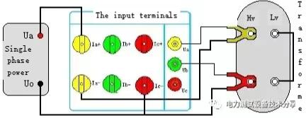
Use a single-phase power supply as the test power supply, the live wire is connected to the positive terminal of the A-phase current terminal of the tester, the thick yellow wire is connected to the negative terminal of the A-phase current terminal, the thin wire is connected to the A-phase voltage terminal Ua, and the thick red wire is connected to the A-phase terminal Ua. Directly connect to the zero line of the test power supply, connect the thin line to the B-phase voltage terminal Ub, and clamp the two pliers to the two terminals on the low-voltage side. The high-voltage side is short-circuited with a special short-circuit wire. Note that the short-circuit must be good, otherwise the test data will be affected.
The method of performing a phase-by-phase short-circuit test on a three-phase transformer with a single-phase power supply is to short-circuit the low-voltage three-phase outgoing terminals of the transformer, and perform three measurements on the high-voltage side. According to the winding connection method of the transformer under test, it can be divided into the following two cases. , see a, b.
a. The pressurized winding is △ connected
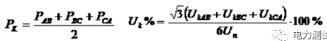
The high-pressure side is pressurized, and the three-phase outlet end of the non-pressurized side (low-pressure side) needs to be manually short-connected. The current in the winding should be 2/picture times the rated current, and the measured value can be converted into three-phase short-circuit loss and short-circuit voltage according to the following formula:
Note: where Un is the rated voltage of the pressurized side
b. The pressurized winding is Y-connected
Pressurize between any two phases in sequence, and at the same time, the three-phase outlet end of the non-pressurized side is manually short-connected.
Note: where Un is the rated voltage of the pressurized side
⑷ Three-phase short circuit test
Wire as shown in the figure:
Note: If the high-voltage or medium-voltage side outlet bushing is equipped with a ring current transformer, the secondary of the current transformer must be short-circuited before the test.
Use the three-phase voltage regulator as the test power supply, connect the output end of the voltage regulator to the positive end of the current terminal of the capacity tester; the thick wires of the three test clamps are respectively connected to the negative end of the current terminal of the tester according to the color; The thin wires of the three test pliers are respectively connected to the voltage terminals of the tester according to their colors. Then clamp three test clamps to the high-voltage side terminal of the transformer under test. The yellow clamp is connected to the A-phase column, the green clamp is connected to the B-phase column, and the red clamp is connected to the C-phase column. Then use a special short-circuit wire to short-circuit the three terminals on the low-voltage side. Note that the short-circuit must be well-connected, otherwise the test data will be affected.
⑸ Zero-sequence impedance test
The impedance shown by the zero-sequence voltage and zero-sequence current of a transformer is called zero-sequence impedance. When the system operates asymmetrically, zero-sequence current will be generated. Its size is not only related to how the windings are connected, but also to the core structure.
For transformer measurement zero-sequence impedance, wire as shown in the figure:
Use a single-phase voltage regulator as the test power supply, connect one output end of the voltage regulator to the positive end of the A-phase current terminal of the loss tester, and the other output end to the negative end of the C-phase current terminal of the tester; yellow test The thick wire of the clamp is connected to the negative end of the A-phase current terminal of the tester, and the voltage test wire is connected to the A-phase voltage terminal; the thick wire of the red test clamp is connected to the negative end of the C-phase current terminal of the tester (that is, with the voltage regulator The outputs are connected together), and the thin wire is connected to the B-phase voltage terminal of the tester. Then short-circuit the A, B, and C-phase terminals of the Yn side wiring method of the transformer under test together, and connect the yellow test clamp; the 0-phase terminal is connected to the red test clamp. Note that it must be well shorted, otherwise it will affect the test data.
Test Steps
1) Three-phase power measurement transformer no-load, load loss test steps
A. Set the test parameters first;
B. Connect the test wires according to the three-phase short-circuit test diagram;
C. Carry out a three-phase short-circuit test and lock the test data;
D. Connect the test wires according to the three-phase no-load test diagram;
E. Carry out three-phase no-load test and lock the test data;
F. Enter the test result screen to view all data;
G. Keep test records.
2) Single-phase power measurement transformer no-load, load loss test steps
A. Set the test parameters first;
B. Connect the test wire according to the single-phase short circuit test diagram;
C. Conduct single-phase short-circuit test;
D. Record short circuit test test results
E. Connect the test wire according to the single-phase no-load test diagram;
F. Conduct single-phase no-load test;
G. Record the test results of the no-load test
Precautions
1. Be sure not to touch the metal parts of the test leads during measurement to avoid electric shock.
2. The measurement wiring must be operated in strict accordance with the instructions, otherwise the consequences will be at your own risk.
3. Before testing, be sure to carefully check whether the set parameters are correct.
4. It is best to use a power outlet with a ground wire.
5. Cannot operate under voltage and current excess limits.
6. During the short-circuit test, the short-circuit on the non-pressurized side must be good, otherwise it will affect the test results.
7. During the short-circuit test, if the high-voltage or medium-voltage side outlet bushing is equipped with a toroidal current transformer, the secondary of the current transformer must be short-circuited before the test.
8. The test wiring work must be carried out under the condition that the tested circuit is grounded to prevent electric shock from induced voltage.All shorts, grounds and leads should have adequate cross-section and must be securely connected. The test organization should be strict and the communication should be smooth to ensure the safe and smooth progress of the test work.
Instrument introduction:
Transformer no-load load characteristic tester is a high-precision instrument specially developed and developed by our company for measuring transformer no-load, load parameters and zero-sequence impedance parameters. It can accurately measure a series of parameters such as no-load current, no-load loss, short-circuit loss, impedance voltage, harmonic content, and distortion rate of various transformers. The instrument has the advantages of small size, light weight, high measurement accuracy, good stability, easy operation and easy learning, etc. It can completely replace the previous method of measuring transformer loss and capacity by using the multi-meter method, with simple wiring, convenient testing and recording, and greatly improved work efficiency. It uses a large-screen graphic real-color LCD as a display window, graphic menu operation and equipped with Chinese characters prompts, a display interface that integrates multiple parameters on one screen, friendly man-machine dialogue interface, easy and fast to use, and is an excellent choice for power users at all levels. Preferred product.
Instrument features:
1. It can measure the no-load current, no-load loss, impedance voltage, load loss and zero-sequence impedance of various types of transformers.
2. Can automatically perform waveform distortion correction, temperature correction (providing simple temperature correction and additional loss correction respectively), voltage correction (no-load test under non-rated voltage), current correction (short circuit under non-rated current conditions) test), it is very suitable for units that do not have short-circuit test conditions for slightly larger-capacity transformers.
3. It can measure three-phase voltage, three-phase current, average voltage, average current, two-phase active power (because the two-power meter method is adopted, only the power of two-phase A and C is displayed here), and total power. 4, It can measure the 2-42 harmonic content of each phase voltage and current and the total distortion rate (harmonic distortion) of each signal.
5. It can display the real-time waveform of each phase voltage and current, and visually display the distortion of the waveform.
6. The voltage loop width limit: the voltage can be measured up to 750V, and the accuracy can be guaranteed without switching gears. The instrument itself will not be damaged due to wrong selection of voltage gear.
7. Large screen, full Chinese character menu and operation prompts realize friendly man-machine dialogue, conductive rubber buttons make operation easier, and high-brightness true-color LCD display can adapt to winter and summer seasons.
8. The user can print the test data through the micro-printer at any time.
9. All test results can be saved in the form of records for future reference.
10. The built-in real clock can display the current date and time in real time, and the test time can be stored at the same time when the record is stored.
Instrument parameters:
1. Input characteristics
Voltage measurement range: 0~750V wide limit.
Current measurement range: 0~5~100A, all internal ranges are automatically switched.
2. Accuracy
Voltage: ±0.2%
Current: ±0.2% of range
Power: ±0.5% (CosΦ>0.1), ±1.0% (0.05<CosΦ<0.1)
3. Working temperature
Working temperature: -10℃~ +40℃
4. Working power
Working power: AC 160V~265V
5. Insulation
(1) The insulation resistance of the voltage and current input terminals to the chassis is greater than or equal to 100MΩ.
(2) The power frequency is 2KV (effective value) between the input end of the working power supply and the casing, and the experiment lasted for 1 minute.
6. Volume: 32cm×24cm×13cm
7. Weight: 3Kg
Instrument picture:

Audited supplier
How to judge and deal with these abnormal phenomena in transformers?
55 Transformer Knowledge You Have to Know
Transformer No-load/Load Test Introduction
What is the main power transformer factory look like
Attending the MIDDLE EAST ELECTRICITY in March
China The Main Power Transformers manufacturers - Canwin
The Knowledge About Power Transformer-Oil Tank Part
The knowledge about "Power Transformer" is all here, Very Comprehensive, Collect it and Learn it!
What impact might the Russian-Ukrainian conflict have on the motor industry? Supplier