The knowledge about "Power Transformer" is all here, Very Comprehensive, Collect it and Learn it!
The Basic Components of A Transformer
1. The basic composition of the transformer
The basic composition of large power transformers is usually divided into the following 7 parts:
1.The core part 1 includes a column, a yoke and a clamping device formed by stacking silicon steel sheets
2.Winding part one includes the lead wires of each phase winding and its connection
3.Insulation part - including oil and paper insulation between each component and its own
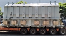
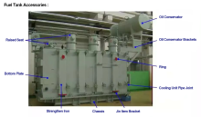
4.Fuel tank part - in addition to the fuel tank itself, it also includes fuel storage tanks, brackets, etc.
5.Cooling system - including cooler or radiator, oil pump, fan, manifold, etc.
6.Measuring instruments - including signal thermometers, current transformers, oil level gauges, etc.
7.Protection devices - pressure releasers, gas relays, moisture absorbers, etc.
Among them, the first two parts can also be called the magnetic circuit part and the circuit part, which are the basic parts.
 Audited supplier
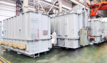
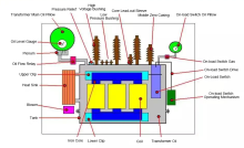
Schematic diagram of the main components of the transformer
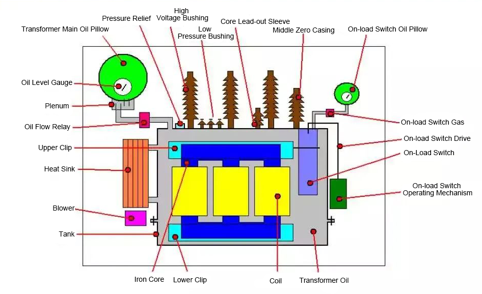
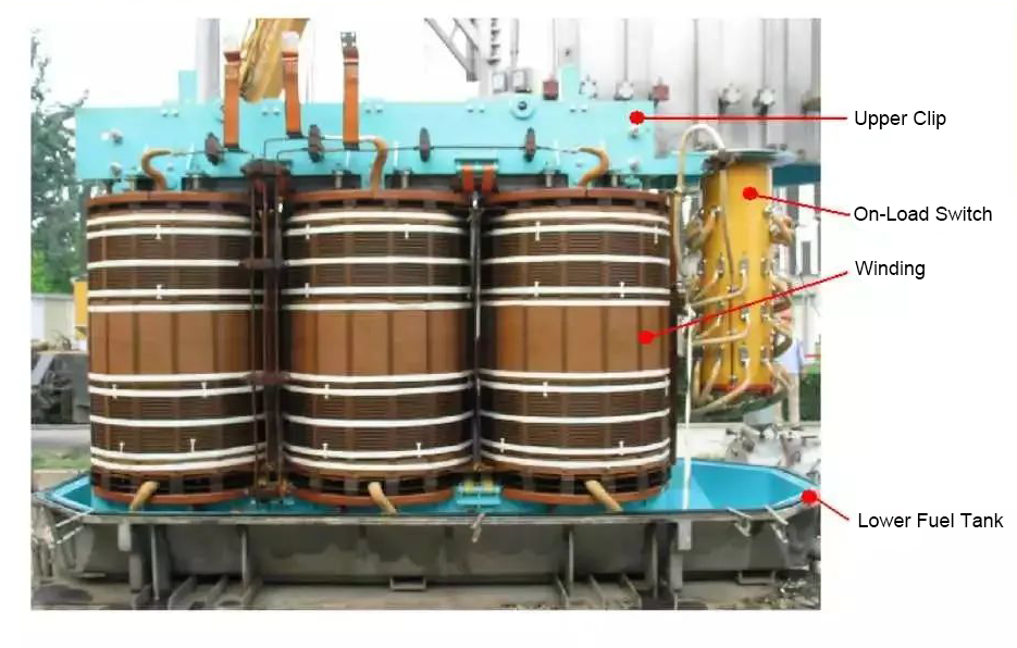
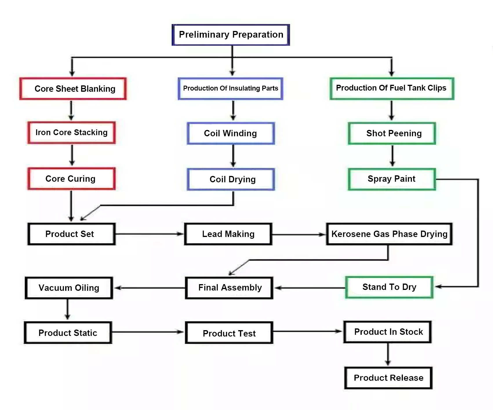
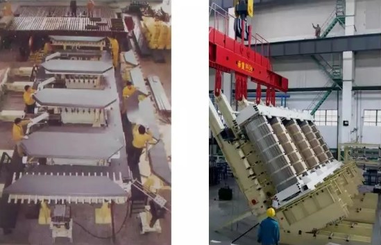
Transformer Manufacturing Process
Transformer core
The main content of the introduction of transformer core is the cutting, stacking, fixing of transformer core and the latest stacking technology to reduce no-load loss.
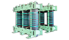
2. Transformer core
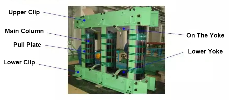
The core is the basic component of the transformer. It consists of a magnetic conductor and a clamping device. It has two functions: in principle, the magnetic conductor of the iron core is the magnetic circuit of the transformer, which converts the electrical energy of the primary circuit into magnetic energy, and from its own magnetic energy into the electrical energy of the secondary circuit, which is the medium of energy conversion. Structurally, the iron core supports all the components inside the transformer, such as the body and leads.
The iron core of the transformer is a frame-shaped closed structure. The part of the coil is called the core column. The part that does not cover the coil and only plays the role of closing the magnetic circuit is called iron giant.
Types of iron cores
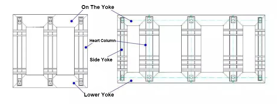
According to the relative position of the winding and the iron core, the iron core can be divided into two categories: core type and shell type. Only the heart-type iron core is introduced here for the time being. For single-phase transformers, the iron core has several structural forms, such as two-column and two-column, single-column four-column, and double-column four-column.
For three-phase transformers, the iron core has several structural forms such as two-column and two-column (three-phase three-column), three-column and four-column (three-phase five-column). The choice of the core structure is determined according to the comprehensive factors such as reasonable arrangement of various windings, material saving, and meeting the transportation height. Bypass can reduce the fifth and seventh wave in the leakage flux and magnetizing current.
Electrical steel strip (silicon steel sheet):
The material used for the iron core magnetic conductor is electrical steel strip with high silicon content, also known as silicon steel sheet.
There are two types of silicon steel sheets: cold rolling and hot rolling, of which cold rolled silicon steel sheets are divided into two types: non-oriented and oriented-
The magnetic properties of hot-rolled silicon steel sheets are poor, the magnetic flux density can only reach 1.5T, and the unit loss is too large, so it is no longer used. Cold-rolled grain-oriented silicon steel sheet has obvious directionality, high saturation magnetic density, small unit loss and unit excitation capacity, and is currently widely used.
The thickness of cold-rolled grain-oriented silicon steel sheet has several specifications, such as 0.35mm, 0.3mm, 0.27mm, 0.23mm, etc. The commonly used one is 0.3mm, and it is getting smaller and smaller, and its main purpose is to reduce no-load transverse loss.
·At present, the main producing areas of silicon steel sheets are Japan, Western Europe, Russia, South Korea and domestic Wuhan Iron and Steel.
The specifications of cold-rolled grain-oriented silicon steel sheets are mainly represented by the thickness and the unit loss (W/kg) when the 50Hz magnetic flux density is 1.7T, for example:
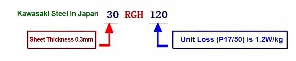
·Newly developed silicon steel sheet using laser irradiation and mechanical engraving technology
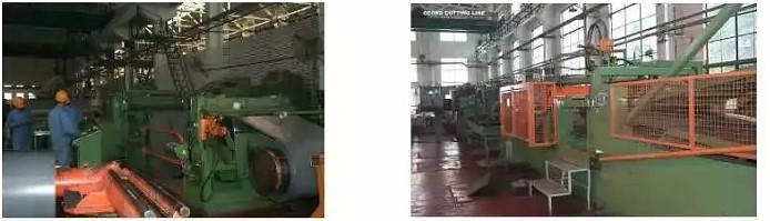
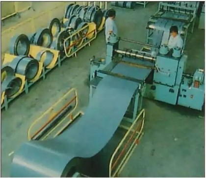
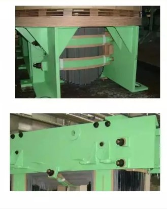
Shearing of transformer core silicon steel sheet:
When the silicon steel sheet material enters the factory, it is a coil with a width of about 1000mm. It needs to be cut into the required shape by special shearing equipment (such as the German Georger wire). The shearing burr of each sheet should not be greater than 0.02mm.
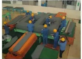
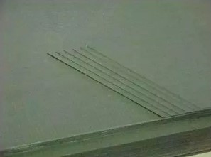
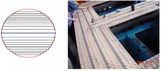
Stacking of iron cores:
●Because the coil of the core type transformer is circular, the section of the core column should also be circular, but it is difficult to manufacture and uneconomical, so it is made into a stepped (graded cylindrical type). Each step forms a rectangle, and the outer limit is located on the same circumcircle. The number of steps has a certain limit, which needs to be comprehensively considered according to the economic benefits.
●When the iron cores are stacked, the core column and the iron core pieces of the iron yoke are alternately lapped together by one or several pieces, so that the butt joints of the upper and lower layers of silicon steel sheets are alternately staggered and cover each other. The excitation current and no-load losses are reduced while improving strength.
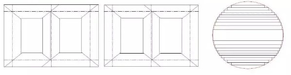
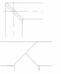
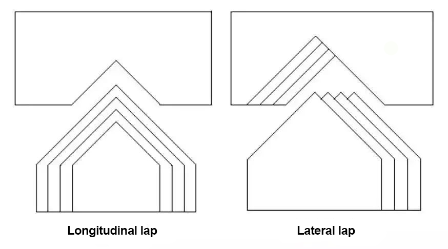
Lap joint of iron core piece:
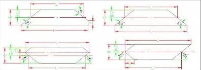
·At present, the transformer core adopts the form of full oblique joint, that is, the junction of the core column and the iron yoke is 45°. This joint form is completely suitable for the characteristics of the high magnetic permeability oriented silicon steel sheet commonly used at present. Make the magnetic circuit as consistent as possible.
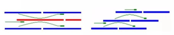
·For large transformer cores with full miter joints, the stacking is generally carried out in the form of two-stage joints. In order to further improve the no-load characteristics of the transformer core, a multi-level seam form of the core is formed, that is, the StepLap core.
In the laminated core, the seams of the silicon steel sheets are staggered. When the magnetic flux of a certain piece encounters the air gap at the seam, the magnetic resistance of the air gap is several thousand times that of the silicon steel sheet. Most of the flux passes through the adjacent silicon steel sheets that bridge this joint. The original magnetic flux of the laminations at the bridging joints and the bridging magnetic fluxes are superimposed. The density may reach saturation, so that the no-load loss and no-load current in the joint area (ie, local) increase sharply, so that the overall no-load loss increases.
Step lap is a new lamination technology adopted this year, which can improve the magnetic density of the silicon steel sheet in the joint area, thereby effectively reducing the no-load loss and noise of the core part.
Core insulation:
The insulation of the iron core has a direct impact on the quality of the transformer core product. The insulation of the iron core can be divided into two parts: the insulation between the sheets and the insulation between the laminations and the structural parts.
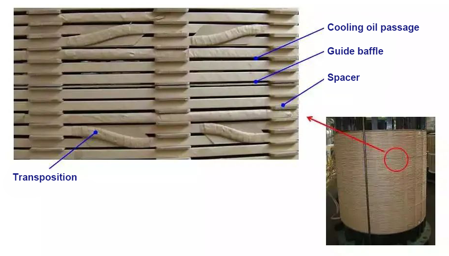
The inter-chip insulation is mainly achieved through two aspects: one is the coating on the surface of the laminated sheet, and the other is to place a layer of insulating cardboard with a certain thickness in each stack during the stacking process, which also acts as a heat dissipation oil channel.
In the large-capacity transformer, in order to make the heat generated in the iron core can be taken away by the transformer oil in the circulation, there are cooling oil passages in the iron core column and the yoke. The oil passages can be punched from silicon steel sheets into corrugated plates or It consists of steel bars welded on silicon steel sheets. For transformer cores with full oblique joints, in order to reduce losses, non-metallic material slats are used to separate oil channels.
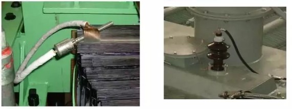
Grounding of the iron core:
During the operation of the transformer, due to the different positions of the iron core and its metal structures in the electric field, the generated potentials are also different. When the potential difference between the two points reaches a certain value, a discharge phenomenon occurs. As a result of the discharge, the transformer oil will be decomposed or the solid insulation will be damaged. In order to avoid this phenomenon, the iron core and its metal structural parts must be effectively grounded.
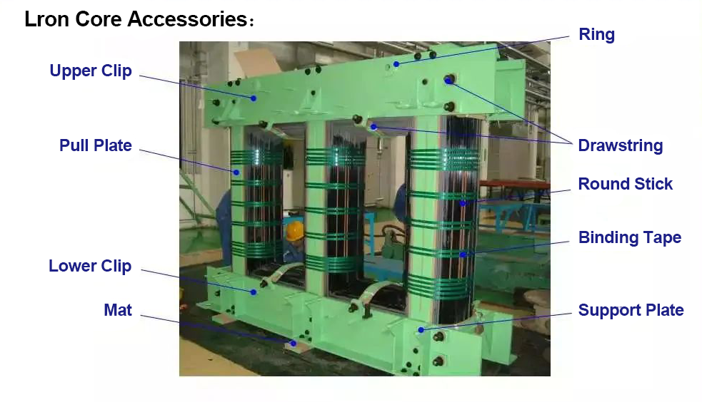
Iron Core Accessories
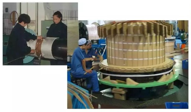
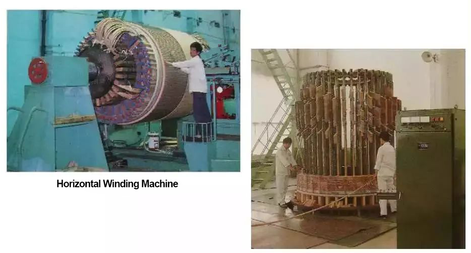
Part II. Transformer winding
The main content of the transformer winding part is the wire and winding method of the transformer winding.
The coil is the electrical circuit of the transformer's input and output electrical energy, and is the basic component of the transformer. Coils must be designed to meet the following basic requirements:
1. Electric strength
Lightning impulse withstand voltage
Operating impulse withstand voltage
Power frequency withstand voltage
2. heat resistance
Under the heat generated by the long-term working current, the service life of the insulation of the coil should not be less than 20 years.
Under the operating conditions of the transformer, a sudden short circuit occurs at any line end, and the coil should be able to withstand the heat generated by the short circuit current without damage.
3. Mechanical strength
coil type;
The coil type is mainly selected according to the relaxation capacity such as the coil voltage, and also considers the electrical strength, mechanical strength, heat dissipation and the feasibility of the manufacturing process. The choice of coil structure is not unique, and sometimes there are several structural forms to choose from. This is also related to the traditional habits of various transformer manufacturers.
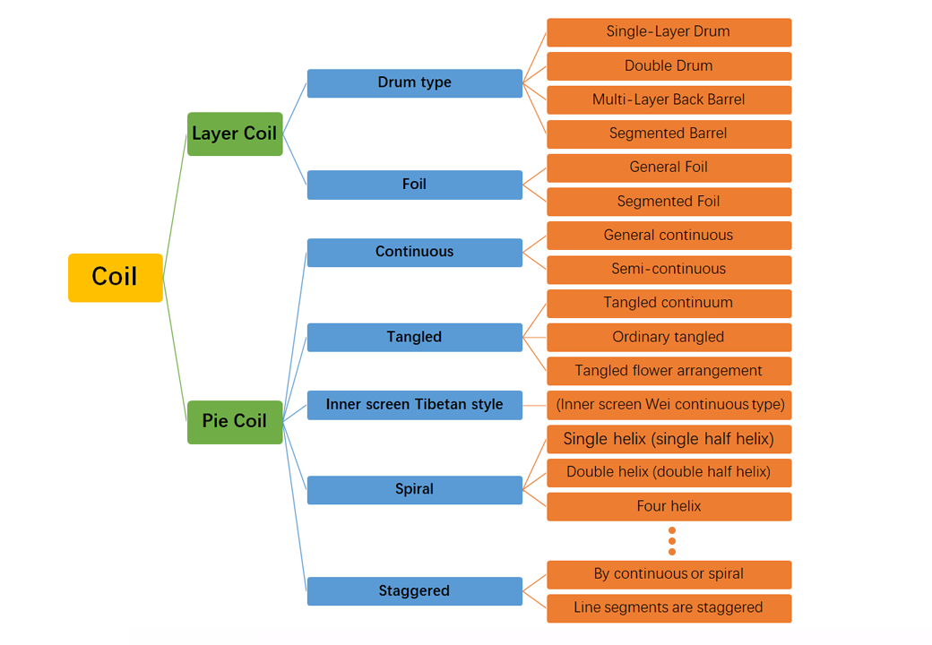
Transformer coils can be roughly divided into two types: layer type and cake type. Pin coils can be divided into spiral, continuous, tangled, tangled continuous, inner shielded continuous and staggered structural types.
Coil Wire:
Winding wire can be divided into copper and aluminum according to different conductor materials, round wire and flat wire according to conductor shape, paper, paint and glass wire according to insulating material. Power transformers usually use paper-wrapped flat steel String.
Paper-covered flat steel wire can be divided into ordinary paper-covered wire, combined wire, transposed wire and other types. According to the tensile strength of steel wire, it can be divided into ordinary wire (00,≤120Mpa), semi-hard copper wire (120Mpa<00.2≤210Mpa). Among them, there is also a self-adhesive transposition wire in the transposition wire, that is, a single flat wire in the transposition wire is coated with a layer of epoxy resin (the thickness of the paint film on both sides is
0.06 ± 0.02mm), the purpose is to stick all the small wires together after the paint film is thermally cured, so as to improve the short-circuit strength of the coil. At present, the latest net package transposition wire has been applied, and corresponding processing production lines have also been introduced in China.
Winding wires can be divided into copper and aluminum according to different conductor materials, round wires and flat wires according to conductor shapes, and paper, paint, and glass wire according to insulating materials. Power transformers usually use paper-wrapped flat copper. String.
Paper-covered flat copper wire can be divided into ordinary paper-covered wire, combined wire, transposed wire and other types. According to the tensile strength of copper wire, it can be divided into ordinary wire (02≤120Mpa), semi-hard copper wire (120Mpa<00, ≤210Mpa). Among them, there is also a self-adhesive transposition wire in the transposition wire, that is, a single flat wire in the transposition wire is coated with a layer of epoxy resin (the thickness of the paint film on both sides is 0.06±0.02mm), the purpose is to heat the paint film. After curing, glue all the small wires together to increase the short circuit strength of the coil. At present, the latest net package transposition wire has been applied, and corresponding processing production lines have also been introduced in China.
Windings are usually divided into two types: layer type and pie type.
The turns of the winding are arranged and wound continuously along the axial direction, which is called a layered winding. Each layer is like a cylinder. Barrel winding.
The turns of the winding are continuously wound in the radial direction to form a pie (segment) shape, and the winding composed of many biscuits arranged in the axial direction is called a pie winding. Including continuous, tangled and inserted capacitive windings.
Common winding forms:
Common windings are cylindrical, spiral, continuous and tangled.
Cylindrical winding is the simplest type, and is generally made of one or several windings. When winding, it is wound one turn close to one turn along the wire mold axis, similar to a circular tightly wound coil spring. It is characterized by simple winding, good workmanship, good heat dissipation of oil passages between layers, but small end support surfaces and poor mechanical strength.
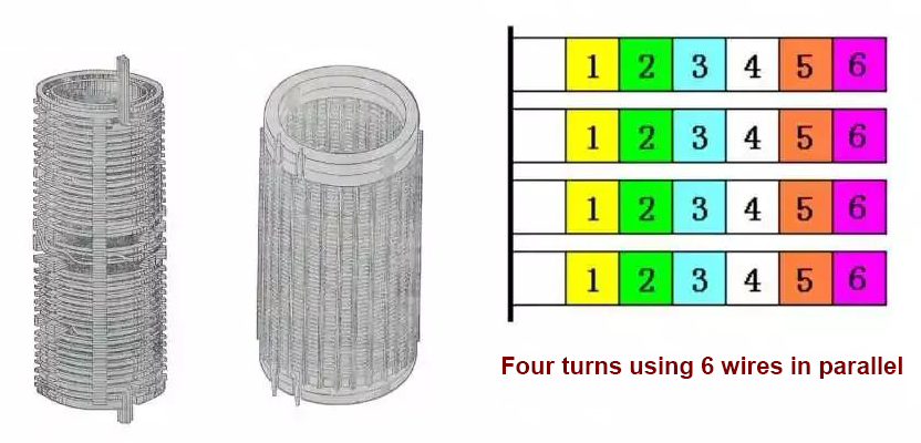
The spiral winding is made of flat wire, and the turns are not close to each other, but are separated by a certain distance (oil channel) with insulating spacers, like a stretched coil spring. The advantage is that the winding process is simple and there is a heat dissipation oil channel, but the winding with a large number of turns is not suitable.
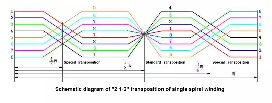
The spiral type consists of multiple wires wound in parallel on the hard tire tube, which can be wound into a single helix type, and can be wound into a double helix or four helix type when there are more parallel wires. When multiple wires are connected in parallel, the wires must be transposed, otherwise there will be a circulating current due to the unequal length of the wires.
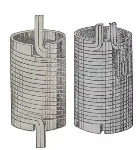
The continuous winding is composed of one or more flat wires that are continuously wound into a plurality of pie-shaped wire segments on the insulating cylinder or wire mold struts through a special process. The advantages are high mechanical strength and good heat dissipation performance. But the winding process is more complicated.
The connection between the continuous wire cake and the wire cake is alternately on the inside and outside of the winding, so as long as the wire length is sufficient, it can be wound into a continuous winding without solder joints.
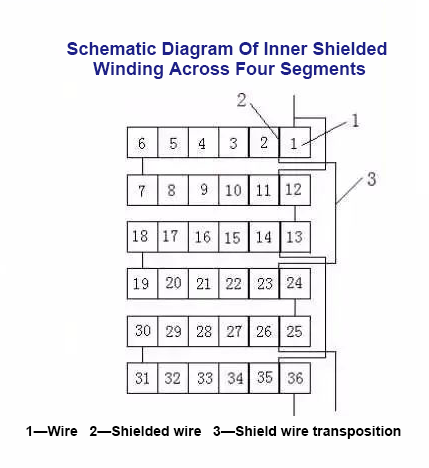
The inserted capacitive winding is formed by inserting a wire (shielded wire) with a longitudinal capacitance between the turns inside the outer side of the continuous winding wire cake. The inserted wire cake and the number of inserted turns can be determined according to the required capacitance. The shielded wire has no The working current is passed through, so very thin wires are usually used.
The inserted capacitive winding adopts continuous winding, which can reduce a large number of welding points compared with the tangled winding, and the number of turns of the inserted shielding wire can be adjusted freely, so that the longitudinal capacitance can be adjusted as required. At present, it is widely used in transformer windings of 110kV and above of large transformers.
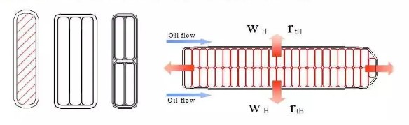
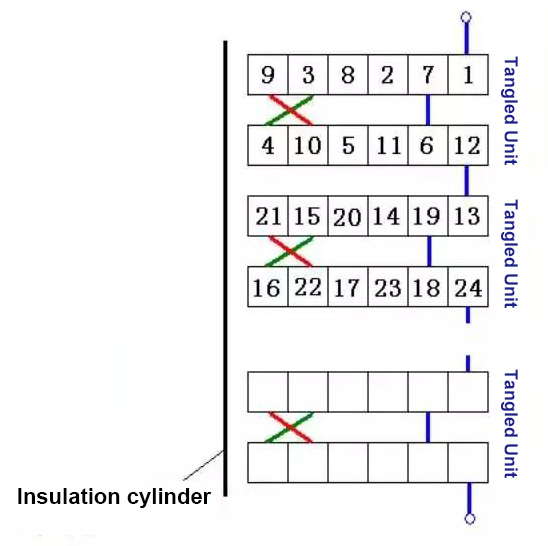
wire transposition
When the transformer current is large, the turns of the coil are composed of multiple parallel wires. If no measures are taken, the wire near the central axis is short, and the wire far from the central axis is long. Due to the different length and position of the wire in the magnetic field, the resistance and inductive reactance of the wire are unbalanced, and the current distribution between the conductors is caused. unbalanced. In order to ensure that the current is evenly distributed along the conductors and reduce additional losses, the parallel conductors must be switched positions, referred to as "transposition".
Audited supplier
How to judge and deal with these abnormal phenomena in transformers?
55 Transformer Knowledge You Have to Know
Transformer No-load/Load Test Introduction
What is the main power transformer factory look like
Attending the MIDDLE EAST ELECTRICITY in March
China The Main Power Transformers manufacturers - Canwin
The Knowledge About Power Transformer-Oil Tank Part
The knowledge about "Power Transformer" is all here, Very Comprehensive, Collect it and Learn it!
What impact might the Russian-Ukrainian conflict have on the motor industry? Supplier