55 Transformer Knowledge You Have to Know
1. What does △/Y0-11 mean on the transformer nameplate?
Answer: According to the different connection methods of the primary coil and the secondary coil of the transformer, the phase angle of the line voltage on the primary side and the secondary side of the transformer is different. Transformer △/ Y0-11 means that the phase angle difference between the two line voltages of the transformer is 330°. It is customary to use the clock notation, that is, 11 o'clock.
 Audited supplier
2. There are often two or more coils in the primary and secondary of the power transformer. If the mark of the same polarity end of the coil is lost, what method can be used to identify it?
Answer: The same polarity end of each coil of the power transformer is usually marked with the symbol "*". If the marker is missing, it can be identified by experimental methods. First connect one low-voltage coil and either end of the other low-voltage coil, then connect any high-voltage coil to the power supply, and use a voltmeter to measure the voltage at the remaining two ends of the two low-voltage coils. If the measured voltage is the sum of the voltages of the two low-voltage coils, it indicates that the connected two ends are not of the same polarity. If the measured voltage is the difference between the two, it indicates that the connected two ends are of the same polarity. The identification method of the polarity of the high voltage coil can be deduced in the same way.
3. If the input voltage of the transformer is excessively greater than the rated voltage, what will be the impact on the transformer?
Answer: Generally, the magnetic flux density of the transformer is high at the rated time, and the iron core is already saturated; if the input voltage is too much larger than the rated voltage, it will cause the iron core to be oversaturated, so that the output voltage waveform will be deformed, so that it contains a large high-order voltage. Harmonic components, cause the output voltage amplitude to increase and make the coil insulation easily damaged. At the same time, the increase of the magnetic flux density increases the iron loss, and the no-load current increases accordingly, causing the transformer to heat up and affecting the power factor of the power grid. Therefore, the input voltage of the transformer is generally not allowed to exceed 5% of the rated voltage.
4. The transformer is a static electrical appliance, but it will make a humming sound during operation, why?
Answer: When the transformer coil is connected to 50 Hz alternating current, a 50 Hz magnetic flux is also generated in the iron core. Due to the change of the magnetic flux, the silicon steel sheet of the iron core also vibrates accordingly, and even if it is clamped, a humming sound of 50 Hz vibration will be generated. But as long as the sound is not aggravated and there are no other noises, it is normal.
5. Why should the through-core clamping bolts of the power transformer core be insulated from the core?
Answer: The iron core of the transformer is composed of silicon steel sheets. In order to reduce the eddy current loss of the iron core, the silicon steel sheets are insulated from each other. If the iron core through bolt is not insulated from the iron core, it will inevitably cause a short circuit at the bolt, which will increase the iron core eddy current loss.
6. Why are the windings in large transformers disc-shaped instead of barrel-shaped?
Answer: Because the short-circuit current of the large transformer is large, the stress generated by the short-circuit is also large, and more supports can be added to the disc winding to prevent the coil from deforming. Large transformers generate more heat, more oil passages in disc windings, and better heat dissipation, while barrel windings only have oil passages between high and low voltages, so heat dissipation is poor. Therefore, the windings of large transformers are all disc-shaped.
7. Why should the coils of large-capacity transformers be transposed?
Answer: The reason why the coil of a large-capacity transformer needs to be transposed is: ① Because the coil of this type of transformer is often wound with several wires in parallel, because the diameter of the coil is large, the lengths of the inner and outer wires are much different, so each wire Wire lengths vary. Transposition can make the length of each wire the same to ensure the balance of coil resistance. ②The conductors of the inner and outer circles have different reactance values due to different magnetic field positions. Transposition is where the wires are positioned similarly in the magnetic field to reduce additional losses in the coil.
8. The coils of the transformer are all immersed in transformer oil, so can the coils of the transformer not be dipped in paint?
Answer: The insulation of the transformer is partly paper, cardboard, cotton yarn, etc., and its insulation performance is improved after immersion in oil. Therefore, only from the perspective of the insulation requirements of the transformer, the transformer can be immersed in transformer oil after vacuum drying, which can achieve a high insulation voltage. However, after the transformer coil is impregnated with paint, the paint film integrates the coil, which increases the mechanical strength, and the electrical conductivity of the cured impregnating paint increases, which improves the heat dissipation of the transformer. The insulation performance is further improved after dipping. Therefore, from the overall requirements, the transformer coil should be dipped in paint.
9. Why is a flexible connection device installed between the busbar connections of the transformer porcelain bushings in the substation?
Answer: This is because the busbar is fixed, and the position of the transformer may move slightly due to maintenance and other reasons. At the same time, the busbar also has the performance of thermal expansion and contraction. After the flexible connection device is installed, the busbar and the transformer can be connected. When the relative position changes slightly, it will not cause great stress to damage the transformer porcelain bushing.
10. Why are the taps of power transformers usually installed on the high-voltage side, while others are installed on the low-voltage side?
A: Since the low side current is much larger than the high side, the wire area required for the tap and the size of the tap changer should increase accordingly. In this way, not only is the lead-out connector inconvenient, but also the installation position has to be increased. The low-voltage coil of the iron-core transformer is on the inside, and it is difficult to draw out the tap from the low-voltage side. At the same time, the number of turns of low-voltage windings is generally less than that of high-voltage windings. Therefore, unless the tap voltage is an integer multiple of the induced voltage of one turn, the tap voltage can be taken correctly. Therefore, the taps of general power transformers are installed on the high-voltage side.
11. Can the neutral bushing of the power transformer used in the power transformer in the high-current grounding system be used with a lower insulation level?
Answer: For power transformers used in high-current grounding systems, the neutral line is always kept at zero potential (except in some fault conditions), but due to the needs of the operating mode, it cannot often be directly connected to ground, so a lower insulation level can be used the casing. Doing so can reduce the cost. But after doing this, the power transformer cannot be subjected to the preventive insulation withstand voltage test according to its rated voltage level, because when the coil is pressurized, the neutral point and the lead wire have the same potential. Therefore, the reliability of the transformer cannot be fully tested in the preventive test.
12. Why use flat tubes instead of round tubes for heat pipes of power transformers?
Answer: When the heat dissipation area of the flat tube is equal to that of the round tube, the insulating oil installed in the flat tube is less than that of the round tube. That is, the oil consumption per unit heat dissipation area of the flat tube is less than that of the round tube, that is to say, the flat tube can use less oil than the round tube to achieve the same heat dissipation effect. Therefore, the current transformer heat pipes use flat pipes instead of round pipes.
13. In order to supplement the oil loss of the transformer during operation, can different grades of transformer oil be added arbitrarily for mixed use?
Answer: When the transformer in operation needs to be supplemented with transformer oil, the type of oil used in the original transformer should be identified first, and then the same grade of transformer oil should be added, because different types of transformer oil cannot be mixed at will. Sometimes when two different grades of transformers need to be mixed (for example, when the same type of oil cannot be found), it is necessary to first understand whether the physical properties of the two oils, such as specific gravity, viscosity, freezing point, flash point, etc., are similar. Then, carry out the stability test, that is, mix the two kinds of oil samples according to the required proportion, put them in the container for one month after mixing, and observe the change; if no sediment is formed, and the mixed oil can reach the insulating oil level. standard can be used.
14. Why can't the coil exposure time be too long when the transformer suspension core is checked?
Answer: The transformer core has been lifted out for a long time. Because the insulating material of the coil has strong moisture absorption performance, the absorption of a large amount of moisture in the air will reduce the insulating performance. In order to prevent moisture from entering the transformer, the temperature of the coil can be made higher than the surrounding temperature when the iron core is hoisted out, and the maintenance should be carried out as soon as possible, and it is not suitable to operate in rainy weather. According to the regulations of the transformer operation regulations, the stay time of the heart in the air is: 16 hours in dry weather (relative humidity of the air does not exceed 65%); 12 hours in wet weather (the relative humidity of the air does not exceed 75%).
15. Why does insulating oil not only require electrical strength, but also require acid value not to exceed a certain value?
Answer: Because when the acid value exceeds a certain value, the insulating oil in the transformer will corrode the solid medium, that is, the insulating material, and cause damage to the insulating material, which will seriously affect the life of the transformer. This is not allowed.
16. Why in some large transformers, the gap of the oil pillow is connected with the gap of the explosion-proof pipe?
Answer: This is to prevent the explosion-proof pipe from being damaged due to excessive air pressure when the temperature of the transformer rises or decreases violently; or the oil level of the explosion-proof pipe and the oil pillow does not reach the same level, causing the gas relay to malfunction.
17. When installing a transformer with a Buchholz relay, should it be installed horizontally or obliquely?
Answer: When installing a transformer with a gas relay, it should be installed obliquely, and the tilt direction is as shown in the figure, that is, the side where the oil pillow is installed should be higher, so that the top cover has a rising slope of 1-1.5% along the direction of the gas relay . In this way, the gas generated in the transformer can easily run to the oil pillow, so as to promote the correct and reliable operation of the gas relay.
18. Transformer, its secondary coil has two windings, and its polarity is unknown. Now how to avoid short circuit by connecting these two windings in parallel?
Answer: Connect either end of the two windings and measure the voltage on the unconnected ends with a voltmeter. For example, the voltage measured by connecting 2 and 3 is the sum of the two secondary voltages, indicating that the two windings are connected in series in this connection, and the wiring must be replaced. If the measured voltage is equal to zero, it means that the connection is correct, and the two vacant ends can be connected and used in parallel.
19. The primary side of two identical Y/Y-12 three-phase transformers are connected in parallel, but the secondary side is not connected in parallel. Is there any voltage between the A phase of the secondary side of the first transformer and the secondary phase B of the second transformer? If the center point of the secondary side of the two transformers is grounded, is there any voltage?
Answer: The secondary of the two transformers are not connected in parallel, and there is no electrical connection, so there is no voltage between the A-phase on the secondary side of the first transformer and the B-phase on the secondary side of the second transformer. If the midpoints of the secondary sides of the two transformers are both grounded, the secondary has an electrical connection, and at this time, there is a voltage, and the voltage is equal to the voltage between phases A and B of the same transformer.
20. Why is one of the primary or secondary sides of a large-capacity three-phase transformer always connected to form a △?
Answer: When the transformer is connected to Y/Y, the 3rd harmonic components of the excitation current of each phase cannot pass through the star connection method without neutral line. At this time, the excitation current still maintains an approximate sine wave. Non-linear, the main flux will have 3rd harmonic components. Since the 3rd harmonic magnetic flux of each phase is equal in magnitude and phase, it cannot be closed by the iron core. Only skilled craftsmen can form a circuit with the help of oil, fuel tank wall, iron yoke, etc. If eddy currents are generated in these parts, it will cause local heating and reduce Transformer efficiency. Therefore, the three-phase transformer with larger capacity and higher voltage should not use the Y/Y connection method.
When the coil is connected to △/Y, the 3rd harmonic component of the primary excitation current can pass, so the main magnetic flux can be kept as a sine wave without the 3rd harmonic component.
When the coil is connected as Y/△, although the 3rd harmonic in the excitation current of the primary side cannot flow, the 3rd harmonic component is generated in the main magnetic circuit, but because the secondary side is connected by △, the 3rd harmonic potential will be The 3rd harmonic circulating current is generated in △. There is no corresponding 3rd harmonic current on the primary side to balance it, so the circulating current becomes the current with excitation properties. At this time, the main magnetic flux of the transformer will be jointly excited by the excitation current of the sine wave on the primary side and the circulating current on the secondary side. △/Y connection is exactly the same. Therefore, the main magnetic flux is also a sine wave without the 3rd harmonic component. In this way, the local heating phenomenon caused by the third harmonic eddy current will not occur after the three-phase transformer adopts the △/Y or Y1/△ connection method.
21. Why can the no-load test of the transformer measure the iron loss, while the short-circuit test can measure the copper loss?
Answer: The iron loss of the transformer includes eddy current loss and hysteresis loss. When the power frequency is constant, it is determined by the magnetic induction intensity in the iron core. The copper loss of the transformer is mainly determined by the current in the primary and secondary coils.
During the no-load test, the secondary side current is zero, the primary side no-load current is very small, and the copper loss can be ignored, while the rated voltage is applied to the primary side, and the magnetic induction intensity in the iron core is the normal value during operation, so the input power is basically consumed in iron loss. During the short-circuit test, the primary and secondary coils are all rated current, while the primary power supply voltage is low, the magnetic induction intensity in the iron core is small, and the iron loss can be ignored, so the input power is basically consumed by the copper loss.
22. Why should the AC withstand voltage test be carried out after heating (60-70℃) for transformers of 110kV and above?
A: Since some air bubbles are generated when the transformer oil is injected, these air bubbles may be attached to the coil, and even a good transformer will cause a discharge accident. In the heating state, not only the bubbles can be removed, but also it is close to the actual operation of the transformer, so the test quality can be guaranteed.
23. Can a transformer in operation be judged by the sound it makes?
A: The transformer can judge the situation based on the sound. Put one end of a wooden stick on the tank of the transformer, and put the other end to your ear and listen carefully to the sound. If it is a continuous "humming" sound, which is heavier than usual, check whether the voltage and oil temperature are too high; if there is no abnormality, check whether the iron core is loose. When the sound of "ZZZ" is heard, check whether there is flashover on the surface of the casing. If there is no abnormality, check the inside again. When the sound of "must be stripped" is heard, check whether the insulation between the coils or between the iron core and the plywood is broken down.
24. When a short-circuit fault occurs on the line connected to the outside of the transformer, what is the impact on the inside of the transformer?
Answer: Due to the external short-circuit fault of the transformer, a large mechanical stress (electric power) is generated inside the coil. This mechanical stress compresses the coil, and the stress disappears after the accident is relieved. This process causes the coil to relax. Insulating pads and backing plates will also loosen or even fall off. When the situation is serious, the insulation of the core clamping screw and the shape of the coil can be changed. When the loose or deformed coil is repeatedly subjected to mechanical stress, the insulation may be damaged, resulting in a short circuit between turns.
25. What is the influence of the no-load transformer opening and closing times on the transformer?
Answer: When the no-load transformer is switched on, the magnetic field in the iron core quickly disappears, and a high voltage will be generated in the coil due to the rapid change of the magnetic field, which may cause breakdown of the weak insulation of the transformer. When the transformer is closed, a large instantaneous overcurrent may be generated, which will cause the coil to be subjected to great mechanical stress, resulting in coil deformation and insulation damage. Therefore, the number of times of opening and closing of the no-load transformer will affect the service life.
26. Why monitor the temperature rise of the transformer? Is the lower the temperature rise the better?
A: The temperature rise of the transformer is one of the important operating parameters. If the temperature rise is too high, the insulation will age quickly, and in severe cases, it will become brittle and rupture, thereby damaging the coil of the transformer; in addition, even if the insulation is not damaged, but the temperature rise is too high, the performance of the insulating material will deteriorate, and it will be easily broken down by high voltage, causing Fault. Therefore, the duty officer of the substation must monitor the temperature rise of the transformer and cannot exceed the allowable temperature of the insulating material. However, the temperature rise of the transformer is not as low as possible, because of the material of a certain insulation level. Allow long-term operation at a certain temperature.
The rated capacity of the transformer is determined according to the allowable temperature of the insulation. Under the rated capacity, the transformer can operate continuously. If the temperature rise of the transformer is too low, it means that the transformer is lightly loaded and the material is not fully utilized, so it is not economical.
27. Why must the iron core of the transformer be grounded, and only one point?
Answer: When the transformer is running, the iron core is in a strong electric field and has a high potential. If it is not grounded, it will inevitably generate a high potential difference with the grounded oil tank, iron yoke, etc., which will lead to discharge and cause transformer accidents. However, if the core silicon steel sheet is grounded at several points, the silicon steel sheet will form along the ground.
The eddy current passage increases the eddy current loss and causes local heating of the iron core, which is also not allowed. Although the silicon steel sheets are coated with insulating paint, their insulation resistance is small, which can only block eddy currents but cannot prevent high-voltage induced currents. Therefore, as long as one piece of silicon steel sheets is grounded, it is equivalent to grounding the entire iron core (commonly known as one-point grounding).
28. For three-coil transformers, what should be paid attention to when the low-voltage coil is open-circuited without load?
Answer: For a three-coil transformer, when the low-voltage coil is running open-circuit without load, attention should be paid to the problem that the insulation of the low-voltage coil may be harmful due to electrostatic induction. Therefore, in this operation mode, the one-phase outlet of the low-voltage coil should be temporarily grounded. If the low-voltage coil is originally equipped with a valve-type arrester, the valve-type arrester can protect this electrostatic induced overvoltage, so there is no need to wear temporary grounding. .
29. When the circuit breaker disconnects the loaded transformer and the no-load transformer, in which case is the transformer more likely to generate overvoltage?
Answer: When the circuit breaker breaks the AC circuit with the load transformer, a large arc will be generated, so generally the arc can be cut off when the alternating current crosses zero. At this time, the energy storage in the transformer inductance is zero; the tiny electric energy in the ground capacitance of the transformer will be quickly released and disappeared through the inductance, so it is not easy to generate overvoltage.
The no-load current amplitude I0 of the no-load transformer is very small, only 1-2% of the rated current, so it has a strong arc extinguishing ability and can cut off a huge short-circuit current circuit breaker. For such a small no-load current, it can be The load is forced to break before the current zero-crossing. At this time, the energy storage in the inductor cannot suddenly change to zero, it will charge the small capacitor of the transformer itself, causing I0 to drop sharply, the current change rate is very large, and the induced potential can reach a very high value, so the circuit breaker cuts off the no-load. The possibility of overvoltage is greater when the transformer is used.
30. The tap changer of the on-load voltage regulator should use two moving contacts K1; K2, the resistance R should be connected in series at the contacts. And the ordinary no-load tap-changer has only one moving contact and the contact does not have a series resistance, why?
Answer: On-load voltage regulation is to extract several taps from the transformer coil, and through the tap changer, under the condition of load, switch from one tap to another, thereby changing the number of coil turns and achieving the purpose of voltage regulation . In the process of voltage regulation, if only one moving contact is used to switch back and forth between the fixed contacts connected to each branch, it will inevitably cause an arc, which will cause an instantaneous power failure after the arc is extinguished. If two moving contacts are used, before switching, the moving contacts K1 and K2 are on the split of 2. When switching, first turn K1 to the split of 1, and then disconnect K2 and 2, so as not to cause power failure, K2 also goes to the 1 position to complete the switch. However, at the moment of the switching process, a loop composed of 2-K2-K1-1 will be formed, which will generate a considerable circulating current. When K2 is disconnected from 2, arc light will be generated, so the current limiting resistor R is connected in series with the moving contact. .
Ordinary no-load tap-changers are switched in the event of a power failure, and there is no problem of power failure and arc generation during the switching process. Therefore, only one moving contact is used and no series resistance is required.
31. Why use the parallel operation mode of transformers? How to achieve parallel?
Answer: With the increase of the power grid capacity, the capacity of one transformer is often unable to bear the full load, and it is not economical to replace the large-capacity transformer, so in order to meet the needs of the user's load, two or more transformers are operated in parallel. In addition, the load of the power grid generally changes with different times of day and night and different seasons of the year. If multiple transformers are operated in parallel, when the load is small, a few less transformers can be put into operation, so that the economical operation of the power grid can be realized; Transformers, which can be serviced in turn without interruption of power supply.
To achieve parallel operation of two or more transformers, four conditions must be met:
(1) The transformation ratio is equal: if two transformers with different transformation ratios are connected in parallel, the secondary sides of the two will generate different voltages, and this voltage difference will generate circulating currents in the loop formed by the secondary sides of the two transformers. will burn out the transformer windings. In order to make the parallel transformers operate safely, my country stipulates that the difference of the transformation ratio of parallel transformers shall not exceed 0.5% (referring to the situation where the tap changer is placed in the same gear).
(2) The wiring groups are the same: if two transformers with different wiring groups are connected in parallel, the voltage phases of the secondary side lines of the two are different, and as a result, a voltage difference will be generated in the parallel secondary side circuit. A large circulating current is generated in the secondary winding, which burns the transformer.
(3) The short-circuit voltage (impedance voltage) is equal: If two transformers with different short-circuit voltages are connected in parallel, the transformer with a small short-circuit voltage is easily overloaded, while the transformer with a large short-circuit voltage cannot be fully loaded. It is generally believed that the short-circuit voltage difference of parallel transformers should not exceed 10%. Usually, try to increase the secondary winding voltage of the transformer with large short-circuit voltage or change the position of the transformer tap to adjust the short-circuit voltage of the transformer, so that the capacity of the parallel-operated transformer can be fully utilized.
(4) The capacity ratio does not exceed 3/1: Because of the large difference in impedance of transformers with different capacities, the load distribution is extremely unbalanced. At the same time, from the perspective of operation, small-capacity transformers cannot play a backup role, so the capacity ratio should not exceed 3. /1. However, the capacity ratio can be greater than 3/1 when both transformers do not exceed the rated load.
32. How to conduct special inspection on transformers?
Answer: When a short-circuit fault occurs in the system or a sudden change of weather occurs, the duty personnel should conduct special inspections of the transformer and its ancillary equipment. The key points of inspection are:
(1) When a short-circuit fault occurs in the system, the transformer system should be checked immediately for bursting, disconnection, displacement, deformation, burnt smell, burning loss, flashover, pyrotechnics and fuel injection.
(2) In snowy weather, you should check whether the lead joints of the transformer have the phenomenon of immediate melting of falling snow or evaporation of gas, and whether there is snow or icicles in the conductive parts.
(3) In windy weather, check the lead swing and whether there is any debris.
(4) In thunderstorm weather, check whether the porcelain bushing has discharge flashover (this inspection should also be carried out in foggy weather), as well as the action of the arrester discharge recorder.
(5) When the temperature changes suddenly, check whether the oil level and oil temperature of the transformer are normal, and whether the wires and joints of the expansion joints are deformed or heated.
33. How to overhaul the off-load tap-changer and on-load tap-changer?
Answer: The tap changer of the transformer is divided into two types: no-load tap-changer and on-load tap-changer. The following first introduces the maintenance points of the no-load tap-changer:
(1) Move the paper insulating sleeve covering the outside of the tap changer upwards, check all parts of the tap changer, whether the leads, insulation and welding are in good condition, and whether the joints are overheated. If the defect is minor, it can be dealt with directly; if there is a serious failure, it should be dismantled or replaced.
(2) Press by hand or check the pressure between the tap changer contact and the contact column with the help of a tool. The pressure should generally be 0.25-0.5Mpa, and any switching part should have good contact. During maintenance, focus on checking the switching parts that are often in operation to see if they are overheated and whether the metal surface is burnt or discolored. If a tap has this phenomenon, and there is no spare part to replace for a while, it can be operated with other tap contacts according to the operating conditions, or the working tap contact can be temporarily welded to become a fixed connection, and then replaced when there are spare parts. resume operation. Burns on the metal surface are often caused by dirty contacts or poor contact. It can be restored to normal working condition by wiping or grinding; if the contacts are severely burned and cannot be repaired, they should be replaced.
(3) Check whether the overall fixing of the tap switch is firm, whether its mechanical operating device is flexible, and whether the operating lever shaft pins are complete and reliable.
(4) Use a bridge measuring small resistance to test the contact resistance of each switching part, which should generally meet the technical requirements of less than 500 microohms; if it is found that the contact resistance of a certain part does not meet the standard, the reasons should be found out and measures should be taken to fix it. eliminate.
After completing the above inspections, eliminating defects and carrying out necessary tests, the tap changer can be placed in the predetermined working position, no longer switched, and the test record of this position can be made.
At present, the transformers with load voltage regulation produced in our country have two types of tap changers: reactive and resistive. The reactive tap-changer is located in the same tank as the transformer body. The resistive tap changer is generally a small oil tank independently placed in the transformer oil tank to place the switching device. The small oil tank is not connected to the oil of the transformer. It has an oil reservoir, a respirator and a gas relay.
The following takes the resistance tap-changer as an example to illustrate the main points of overhauling the on-load tap-changer:
(1) Open the top cover of the small fuel tank equipped with the switching device, and remove the winding tap connecting wire and fixing bolts.
(2) Take out the switching device of the on-load tap-changer, check the welding quality of the lead wire, whether the bolt connection is loose, whether there is burns and overheating in operation, whether the insulation of the lead wire is damaged, and whether the conduction of the moving and static contacts of the switch is good. , with or without singeing.
(3) Switch gear by gear, and test the contact resistance of the contact, and its value should be less than 500 microohms.
(4) Check whether the fixed resistance is broken or damaged, measure whether its resistance value changes, whether the insulating plate is damaged, and use a megohmmeter to measure the insulation resistance of the live part in operation.
(5) Check whether the rotating shaft and the fixed plate of the movable insulating plate are reliable, whether the energy storage spring of the mechanical rotating part is broken, whether the mechanical parts such as the transmission shaft and pins are dropped and damaged, and whether the teeth of the worm gear and worm are excessively worn. .
(6) The reversible motor should be disassembled and repaired.
(7) The oil in the small oil tank is burned by the arc due to the multiple switching of the switching device, resulting in carbon particles. In order to ensure the heat dissipation performance and insulation performance of the oil, the deteriorated oil should be replaced in time, and before the new oil is injected, the oil tank should be checked for seepage and leakage, and the pollution and debris at the bottom of the tank should be removed at the same time.
After the maintenance is completed, it should be assembled in time, and then the power-on test of the motor and the switching test of the tap changer should be carried out. In order not to let the parts get wet, the tap-changer should not be exposed to the air for too long.
34. What are the inspection items of the tap changer?
Answer: (1) The voltage indication should be within the voltage deviation range;
(2) The power indicator of the controller shows normal;
(3) The tap position indicator should be incorrect;
(4) The oil level, oil color, temperature absorber and its desiccant of the tap changer oil conservator are all normal;
(5) There should be no oil leakage in all parts of the tap changer and its accessories;
(6) The counter operates normally, and the number of tap changes is recorded in time;
(7) The interior of the motor mechanism box should be clean, the lubricating oil level should be normal, the mechanism box door should be tightly closed, moisture-proof, dust-proof, and well-sealed against small animals;
(8) The tap changer heater should be in good condition and switched in time as required.
35. What are the inspection and maintenance of the switch?
Answer: (1) Check whether the fasteners are loose;
(2) Check whether the main spring, return spring and claw of the quick mechanism are deformed or broken;
(3) Check whether the braided flexible connecting wire of each contact has broken strands;
(4) Check the degree of burning of the moving and static contacts of the switch;
(5) Check whether the transition resistance is broken, and measure the DC resistance at the same time. Compared with the data on the product nameplate, the deviation value of the resistance value is not greater than +/-10%;
(6) Measure the loop resistance between the single, double and neutral lead points of each phase, and the resistance value should meet the requirements;
(7) Measure the action sequence of switching moving and static contacts, and all action sequences should meet the technical requirements of the product.
36. How to carry out external inspection on the transformer in operation?
A: The external inspection of the transformer can be carried out without power failure, and the abnormal phenomenon of the transformer can be found in time. In general, the following items should be detected during inspection:
(1) The oil color in the transformer oil pillow and the oil-filled bushing (if the structure of the oil-filled bushing is suitable for inspection), the oil level, and whether there is seepage or leakage; whether there is water in the mud collector of the oil pillow And dirt, if any, should be drained by opening the bottom plug.
(2) Whether the transformer bushing is clean, whether there are cracks, discharge traces and other abnormal phenomena.
(3) The nature of the hum of the transformer, whether the sound increases, and whether there is any new abnormal sound.
(4) Whether the grounding of the transformer oil tank is in good condition.
(5) Whether the cables and busbars are abnormal.
(6) Whether the operation of the cooling device is normal.
(7) The oil temperature of the transformer is high or low.
(8) Whether the diaphragm of the explosion-proof pipe is complete; whether the desiccant in the moisture absorber absorbs moisture to a saturated state.
(9) Check the oil level of the gas relay and whether the accelerator is open.
(10) If the transformer is installed indoors, check whether the doors and windows are intact, whether the house is leaking, whether the lighting brightness is sufficient, and whether the room temperature is suitable.
In addition, according to the structural characteristics of the transformer, other related items can also be checked.
37. What are the inspection items in the main transformer, unit transformer and startup transformer running?
1) Winding temperature and oil temperature
2) Oil level of oil pillow
3) Operation of the respirator device
4) Hydrogen monitoring value
5) Whether the body has abnormal vibration, sound and smell
6) Whether there is seepage and oil leakage in each part of the transformer
7) The oil level of the high-voltage bushing is normal, the skirt is intact, and there is no serious discharge phenomenon
8) The oil pump and fan of the cooler are running normally, and the oil flow indication is correct
9) The local control panel is well sealed and free from deformation, and the peep glass is intact
10) Transformer shell, arrester, and neutral grounding device are in good condition
11) The arrester porcelain skirt is in good condition, and whether the value of the register has changed
12) Start to change the oil pressure of the high-voltage oil-filled cable
38. How to conduct special inspection on transformers?
Answer: When a short-circuit fault occurs in the system or a sudden change of weather occurs, the duty personnel should conduct special inspections of the transformer and its ancillary equipment. The key points of inspection are:
1) When a short-circuit fault occurs in the system, the transformer system should be checked immediately for bursting, disconnection, displacement, deformation, burnt smell, burning loss, flashover, pyrotechnics and fuel injection.
2) In snowy weather, you should check whether the lead joints of the transformer have the phenomenon of snow melting or evaporation immediately, and whether there is snow or icicles in the conductive parts.
3) In windy weather, check the lead swing and whether there is any debris.
4) In thunderstorm weather, check whether the porcelain bushing has discharge flashover (this inspection should also be carried out in foggy weather), and the action of the arrester discharge recorder.
5) When the temperature changes suddenly, check whether the oil level and oil temperature of the transformer are normal, and whether the wires and joints of the expansion joints are deformed or heated.
39. What are the inspection items for dry-type transformers?
1) Winding temperature
2) Whether there is abnormal vibration, sound and smell
2) The transformer room door is in good condition
40. What are the inspection items for electrostatic precipitator rectifier transformer and first-level cycle transformer?
1) Transformer oil temperature
2) Oil level of oil pillow
3) The color of the desiccant in the respirator is normal
4) Whether the body has abnormal vibration, sound and smell
5) Whether there is oil leakage in each part of the transformer
6) The transformer shell is well grounded
7) Whether there is water leakage and safety-threatening sundries around the transformer
41. How to overhaul the off-load tap-changer and on-load tap-changer?
Answer: The tap changer of the transformer is divided into two types: no-load tap-changer and on-load tap-changer. The following first introduces the maintenance points of the no-load tap-changer:
1) Move the paper insulating sleeve covering the outside of the tap-changer upwards, check all the parts of the tap-changer, whether the leads, insulation and welding are in good condition, and whether the joints are overheated. If the defect is minor, it can be dealt with directly; if there is a serious failure, it should be dismantled or replaced.
2) Press by hand or check the pressure between the tap changer contact and the contact column with the help of a tool, the pressure should generally be 0.25-0.5Mpa, and any one cut
The switching parts should have good contact. During maintenance, focus on checking the switching parts that are often in operation to see if they are overheated and whether the metal surface is burnt or discolored. Overheating is mostly due to the long-term operation of the pressure spring of the tap changer. , caused by the decrease in elasticity;
42. What principle are used to make the main transformer, unit transformer and start transformer refrigerated respirator?
It is made by using the principle of thermoelectric cooling effect of semiconductor materials
43. What is a split transformer and what is the split coefficient of a split transformer? Where does the factory use split transformers?
One or several coils in the coil of the transformer are split into several branches that are not connected to each other, and each branch can run independently or at the same time. This kind of transformer is called a split transformer. The ratio of the split impedance to the through impedance is called the split coefficient. The unit transformer and start-up transformer of our factory all use split transformers.
44. What are the advantages and disadvantages of split transformers? How many modes of operation are there for a split transformer?
1) It can effectively increase the impedance and limit the short-circuit current on the low-voltage side, so light switchgear and cables can be selected to save investment.
2) When the split transformer is running, when one low-voltage coil is short-circuited, the busbar voltage of the other low-voltage coil decreases very little, which can maintain normal operation.
3) When the load of one low-voltage coil changes, the normal bus voltage fluctuation has no effect on the other low-voltage coil.
45. What is the role of main transformer, plant high transformer and starting transformer?
The function of the main transformer is to increase the output voltage of the generator and send the electric energy to the power system for system users.
The function of the plant height change is to reduce the output voltage of the generator and send the electric energy to the plant system to supply the plant load.
The function of the starting transformer is to reduce the system voltage and send the electric energy to the factory system to supply the factory load, which is used when the unit starts, stops or has an accident.
46. What are the maintenance contents of the transformer cooling device?
1) Check the cooling oil pump and fan motor (including sound, leakage, vibration, smooth oil circuit and whether the fan blade is deformed, etc.), and carry out maintenance.
2) Check and clean the operation circuit of the cooling device and the flexibility of the automatic start-stop device to eliminate the existing defects.
Thoroughly clean the cooler radiator pipes.
4) Check the cooling device meter.
47. What does the short-circuit loss of the transformer refer to?
The no-load loss of the transformer is divided into the active part and the reactive part. The active part is the loss generated when the resistance of the primary and secondary windings of the transformer passes through the current; the reactive part is mainly the loss caused by the leakage flux.
48. What does the unbalanced current of the transformer refer to? What is the cause?
The unbalanced current of a transformer refers to the current difference between the three-phase transformer windings. The main reason is that the three-phase loads are not the same.
49. What are the factors that affect the oil temperature of the transformer?
The factors affecting the oil temperature of the transformer include the size of the load, the level of air temperature, the cooling method and cooling power, the smoothness of the oil circuit and the amount of oil, and the size of the heat dissipation surface of the box wall.
50. What is gas chromatography?
Gas chromatography is a new type of physicochemical separation analysis method developed rapidly in modern times. In the analysis process, gas is used as a carrier gas to separate the mixed gases with different characteristics to be analyzed and then qualitatively and quantitatively. The full name of this analysis is called gas chromatography.
51. For different types of faults, which characteristic gases are contained in the gas components?
In the discharge fault, the gas component contains a certain amount of acetylene; the bare metal is overheated, and the gas component contains a large amount of hydrocarbon gas and less carbon monoxide and carbon dioxide; the failure of solid insulation overheating, in addition to the generation of hydrogen and hydrocarbon gas, Mainly carbon monoxide and carbon dioxide components.
52. How to calculate transformer efficiency? What factors is it related to?
Answer: The difference between the output power of the transformer and the input power is called the power loss (η) of the transformer, and its calculation formula is
η=P2/P1×100%
where P1 is the input power, kilowatts;
P2 is the output power, kilowatts.
The difference between the input power and the output power of the transformer is called the power loss of the transformer, that is, the sum of copper loss and iron loss, and its calculation formula is
P1=P2+△Pti+△Pto
where △Pti is the iron loss of the transformer;
△Pto is the copper loss of the transformer.
So η= P2/P1×100%= P2/(P2+△Pti+△Pto)×100%
When the voltage is constant, the iron loss is constant, so the efficiency of the transformer is related to the copper loss, and the copper loss
△Pto=I12R1+I22R2
where I1R1 is the high-voltage side current and the high-voltage winding resistance, respectively;
I2R2 is the low-voltage side current and the low-voltage winding resistance, respectively.
In this way, the efficiency of the transformer is related to the size and nature of the load. Usually, the efficiency of the transformer is very high (up to 95-99%). For the same transformer, when the load is small, the efficiency is low; when the load is about 60% of the rated value, the efficiency is high.
53. How to calculate the phase and line current and phase and line voltage of the transformer?
Answer: Now a 10/0.4kV, Y/Y0-12 wiring, rated capacity is 400kV. Taking a transformer as an example, the phase and line voltages are calculated as follows:
Se=√3 UeIe or Se=3UφIφ
In the formula: Se is the rated capacity of the transformer, KVA. Ue is the line voltage, KV. Ie is the line current, A. Uφ is the phase voltage, V. Iφ is the phase current, A.
It can be seen from the above formula that:
Primary line current Ie1=Se/(√3 Ue)=400/(√3×10)=23.1(A)
Since it is a Y-shaped connection, the phase and line currents are equal, that is, Ie=Iφ, the primary phase current Iφ1=23.1 (A),
Primary line voltage = 10KV.
The primary phase voltage is: Uφ1= Ue1/√3 =10/√3 =5.8(KV)
The secondary line current is: Ie2 = Se/(√3)=400/(√3×0.4)=578(A)
The secondary phase current is: Iφ2=Ie2=578 (A)
The secondary line voltage is: Ue2=400 (V)
The secondary phase voltage is: Uφ2= Ue2/√3 =400/√3 =231(V).
54. A transformer with a model of SFPL—120000/220, the high voltage side voltage is 242+2×2.5%KV, the low voltage side rated voltage is 10.5KV, and the line group is YO/△-11, find the high and low voltage sides What is the rated phase current?
Solution: I1X=I1e=Se/(√3 U1e)=120000/(√3 ×242)=286(A)
(The high voltage side is the YO wiring method)
I2X= I2e/√3 = Se/(√3 U2e/√3 )= Se/(3 U2e)=120000/(3×10.5)=3810(A)
where:
I1X, I2X—respectively the rated phase current of the high and low voltage sides of the transformer (A)
I1e, I2e—respectively the rated current of the high and low voltage sides of the transformer (A)
U1e, U2e—respectively the rated voltage of the high and low voltage sides of the transformer (A)
Se—the rated capacity of the transformer (KVA)
55. A transformer whose wiring group is Y/△-11 three-phase has a rated voltage of 121KV/10.5KV and a capacity of 120000KVA. What is the rated current of the high and low voltage sides? If the wiring is changed to Y/Y-12, has the capacity changed? At this time, what is the rated current of the low-voltage side, and what is the rated voltage?
Solution: When Y/△-11:
Se=√3 I1e U1e
I1e=Se/(√3 U1e)=120000/(√3×121)≈573(A)
Since the transformer is very efficient, it can be seen as lossless in this computer, i.e.
Se=√3 I2e U2e
I2e=Se/(√3 U2e)=120000/(√3×10.5)=6600(A)
When the wiring is changed to Y/Y-12, its capacity remains unchanged.
When changing to Y/Y-12:
U'2e=√3 U2e=√3 ×10.5=18.2(KV)
When the Y-connection is used, the line voltage is √3 times the phase voltage
I'2e=Se/(√3 U'2e)=120000/(√3 ×√3 ×10.5)=3810(A)
Se—the rated capacity of the transformer (KVA)
I1e, I2e—respectively the rated current of the high and low voltage sides of the transformer at Y/△-11 (A)
U1e, U2e—respectively the rated voltage of the high and low voltage sides of the transformer when Y/△-11 (A)
I'2e, U'2e—respectively the rated current (A) and rated voltage (A) of the high and low voltage sides of the transformer Y/Y-12.
Source: Internet
Audited supplier
How to judge and deal with these abnormal phenomena in transformers?
55 Transformer Knowledge You Have to Know
Transformer No-load/Load Test Introduction
What is the main power transformer factory look like
Attending the MIDDLE EAST ELECTRICITY in March
China The Main Power Transformers manufacturers - Canwin
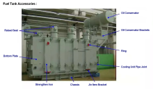
The Knowledge About Power Transformer-Oil Tank Part
The knowledge about "Power Transformer" is all here, Very Comprehensive, Collect it and Learn it!
What impact might the Russian-Ukrainian conflict have on the motor industry? Supplier