About Canwin Do you want to know how the transformers structure combined? user manual | Canwin
Transformer body structure
This paper mainly introduces the structure of transformer body from three aspects: core, winding and lead.
I.Transformer core structure
01 The role of silicon steel(Iron) core
Transformers are based on the principle of electromagnetic induction, the magnetic circuit is the medium of electrical energy conversion. Iron core is the main magnetic circuit of the transformer, the main role is magnetic. It converts the electrical energy of the primary circuit into magnetic energy, and from magnetic energy into electrical energy of the secondary circuit.
At the same time, the iron core is the mechanical skeleton of the transformer, and the clamping device of the iron core not only makes the magnetic conductor into a mechanical complete structure, but also has an insulated coil on it, supporting the lead, and almost all the components inside the transformer. The weight of the iron core is the largest in the transformer components, accounting for about 60% of the total weight in the dry transformer, and about 40% in the oil-immersed transformer.
 Audited supplier
02 Iron core form
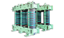
The iron core consists of an iron core column and an iron yoke. The iron core column is covered with windings and the iron yoke connects the iron core column to form a closed magnetic circuit.
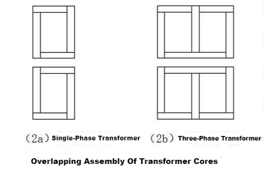
FIG. 1A is a single-phase transformer, FIG. 1B is a three-phase transformer. The iron core structure can be divided into two parts, C is the part of the coil, known as the core column. Y is the part used to close the magnetic circuit, called the iron yoke. Single-phase transformer has two core pillars, three-phase transformer has three core pillars.

Because the magnetic flux in the transformer iron core is an alternating flux, in order to reduce eddy current loss, the transformer iron core is generally made of a certain size of iron chip made of silicon steel sheet with high resistivity. The silicon steel sheet composed of the iron core is first cut into the required shape and size, namely the punching sheet, and then combined with the punching sheet in an overlapping way. Figure 2A shows the iron core of a single-phase transformer. Each layer consists of 4 blanking sheets. FIG. 2b shows the iron core of three-phase transformer, each layer is composed of 6 pieces, and the combination of punch pieces of each two layers applies different arrangement methods to stagger the joint of magnetic circuit of each layer. This assembly method is called overlapping assembly, which can avoid eddy current flowing between steel sheets. And because the layers are interlaced and inlaid, fewer fasteners can be used to make the structure simple when the core is pressed. When assembling, the punch pieces are first overlapped to form a whole iron core, then the lower yoke is clamped, the upper yoke punch pieces are pulled out to expose the iron core column, the prefabricated windings are set on the iron core column, and finally the drawn upper yoke punch pieces are inserted.
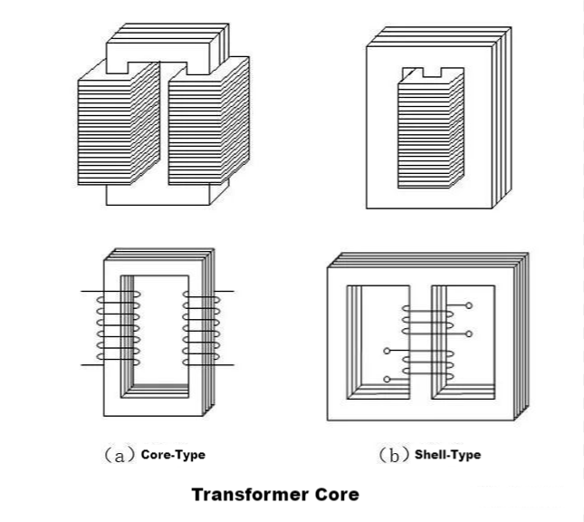
According to the layout of winding in the core, the transformer is divided into core and shell type two. The difference is mainly in the distribution of magnetic circuit, shell transformer core yoke surrounded the coil, core transformer core in most of the coil, only part of the coil outside the iron yoke, used to form a magnetic loop.
03 Heat dissipation of iron core
When the transformer is in normal operation, the iron core will generate heat because of the iron loss, and the greater the weight and volume of the iron core, the more heat will be generated. Transformer oil temperature above 95 degrees is easy to aging, so the temperature of the core surface should be controlled below this temperature as far as possible, which requires the heat dissipation structure of the core to quickly emit the heat of the core. The heat dissipation structure is mainly to increase the heat dissipation surface of the core. The heat dissipation of iron core mainly includes heat dissipation of iron core oil channel and heat dissipation of iron core airway.
In large capacity oil-immersed transformers, oil grooves are often set between the laminates of the iron core to enhance the heat dissipation effect. The oil groove is divided into two types, one is parallel to the silicon steel sheet and the other is vertical to the steel sheet, as shown in FIG. 4. The latter arrangement has better heat dissipation effect, but the structure is more complex.

The iron core of the dry transformer is air-cooled. In order to ensure that the temperature of the iron core does not exceed the allowable value, the air duct is often installed in the iron core column and iron yoke.
04 Noise of iron core
Transformers produce noise during operation. The source of transformer noise is magnetostriction of iron core silicon steel sheet, or the noise of transformer core is basically caused by magnetostriction. Magnetostriction refers to the increase of the size of the silicon steel sheet along the magnetic induction line when the iron core is excited. The size of the silicon steel sheet decreases in the direction perpendicular to the magnetic induction line, which is called magnetostriction. In addition, the structure and geometric size of the iron core, and the processing and manufacturing technology of the iron core will have a certain degree of influence on the noise level.
The noise level of the iron core can be reduced by the following technical measures:
(1) Use high quality silicon steel sheet with small magnetostrictive ε value.
(2) Reduce the magnetic flux density of the core.
(3) Improve the structure of the iron core.
(4) Choose a reasonable core size.
(5) Adopt advanced processing technology.
05 Grounding of iron core
In normal operation of the transformer, the electric field formed between the electrified windings and leads and the oil tank is an uneven electric field, and the iron core and its metal parts are in this electric field. Due to the electrostatic induction potential is not the same, so that the suspension potential of the iron core and its metal components is not the same, when the potential difference between two points can break down the insulation between them, spark discharge will be generated. This discharge can break down the transformer's oil and damage the solid insulation. To avoid this, both the core and its metal components must be reliably grounded.
The core must be grounded at one point. When the iron core or other metal components have two points or more than two points of grounding, the ground point will form a closed loop, the formation of circulation, the current can sometimes be as high as tens of an, will cause local overheating, lead to oil decomposition, may also make the grounding element fuse, burn out the iron core, these are not allowed. Therefore, the core must be grounded, and a little grounded.
II. Transformer winding structure
Function of 01 winding
Winding is the most basic part of the transformer, is the establishment of magnetic field and transmission of electric power circuit part, generally wrapped with insulating paper copper wire or aluminum wire wound, and set in the transformer core column. The transformer core should have sufficient insulation strength, mechanical strength and heat resistance.

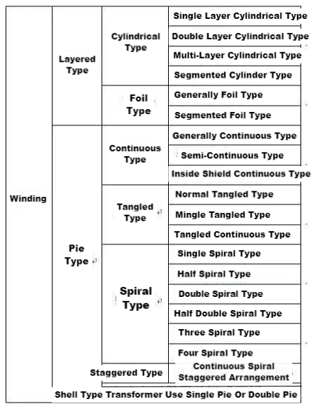
Type of winding
Transformer winding structure can be generally divided into two categories: layer structure and cake structure. The layer structure refers to that the winding turns along its axis are arranged continuously, generally used in S8 and S9 series of low loss power transformers; The cake structure refers to that the turns of the winding are continuously wound into a cake (segment) along its radial direction, and then composed of many cakes arranged along the axial direction. It is generally used in large and extra-large transformers with high voltage of 110kV and above.
Basically, the windings of power transformers produced in China adopt concentric structure. Concentric winding means that the windings are wrapped outside the core column with the same cylindrical line at any cross section of the core column. There must be a certain insulation gap and heat dissipation channel (oil channel) between the high and low voltage windings and between the low voltage windings and the iron core column, separated by insulated cardboard tube. The insulation distance depends on the voltage level of the winding and the clearance required by the heat dissipation channel. When the low-voltage winding is placed inside close to the core column, the required insulation distance between it and the core column is relatively small, so the size of the winding can be reduced, and the overall size of the transformer is also reduced.

The three winding transformer is most commonly used in power system. Using a three-winding transformer to connect the transmission system with three different voltages is more economical, occupies less land and has more convenient maintenance and management than using two common transformers. Three-phase three-winding transformer usually adopts Y-Y-△ connection, that is, the primary and secondary windings are Y connection, and the third winding is △, as shown in Figure XX. △ connection itself is a closed loop, through the same phase of the third harmonic current, so that the Y connection primary, secondary winding does not appear in the third harmonic voltage. In this way it provides a neutral point for both primary and secondary sides. In the long distance transmission system, the third winding can also be connected with synchronous camera to improve the power factor of the line.

III. Transformer lead structure
01 Lead material and classification
Transformer windings are connected externally to the leading end of the wire is called the lead, through the lead to the external power supply power input transformer, but also through the lead transmission in the electrical power output from the transformer to the outside.
There are mainly the following types of leads:
(1) the lead wire connected with the winding wire end and the casing;
(2) connecting leads between winding ends;
(3) the winding tapping is connected with the tapping lead connected with the switch
The lead material is generally:
(1) Bare copper bar, applicable scope: 10kV class 6300kVA and below transformer;
(2) Paper wrapped round copper bar, applicable scope: 10 ~ 35kV small capacity transformer;
(3) Bare copper bar, applicable scope: 10kV and below low-voltage winding leads;
(4) Copper stranded wire, applicable scope: all voltage levels, especially 110kV and above the lead;
(5) Copper pipe, scope of application: 220kV and above transformer lead.
In order to ensure sufficient insulation distance, the lead through laminate wood, cardboard insulation, must meet the requirements of electrical performance, mechanical strength, temperature rise. The selection of leads is also based on electric field strength and mechanical strength, as well as short-circuit temperature rise and long-term load temperature rise these aspects to select.
02 Connection of lead
Transformer lead connection forms are: brazing, gas welding, cold pressure welding and bolt connection.
The electrode of brazing shall be made of phosphor copper alloy for the connection between the winding outlet and the lead and between the leads.
Gas welding is used for welding copper bar lead wire and cable piercing casing joint.
Cold pressure welding is to insert the two terminals connected by the lead into a metal tube, and then use a mold to squeeze the metal tube, the two terminals pressed together. Cold pressure welding does not need heating, welding is relatively safe, there is no false welding, and burn leads and other parts of insulation, extrusion quality, good tensile strength. Therefore, cold pressure welding is the main way of lead connection for large transformers.
The bolt connection is mainly used for the lead wire connected with the guide rod sleeve. The lead wire can be disassembled and can compensate for the deviation of the lead length. Usually, the curved arc lead structure can be free to expand, also known as the soft connection.
03 Fastening of the lead
In order to ensure the insulation distance of the lead, and withstand the vibration and impact of electric power during operation and short circuit without displacement and deformation, clamping parts must be used to tighten the lead.
Lead clamping parts should have enough mechanical strength and electrical strength, so the lead clamping part structure generally adopts wood support structure, clamping parts and transformer body metal parts are fixed, in order to improve the mechanical strength of metal bolts available, but between the clamping parts must be fixed with epoxy bolts, and there is a loose device. Insulation board should be added to clamp the lead as additional insulation to prevent the lead from being jammed.
FAQ
Advantages
About Canwin
Audited supplier
How to judge and deal with these abnormal phenomena in transformers?
55 Transformer Knowledge You Have to Know
Transformer No-load/Load Test Introduction
What is the main power transformer factory look like
Attending the MIDDLE EAST ELECTRICITY in March
China The Main Power Transformers manufacturers - Canwin
The Knowledge About Power Transformer-Oil Tank Part
The knowledge about "Power Transformer" is all here, Very Comprehensive, Collect it and Learn it!
What impact might the Russian-Ukrainian conflict have on the motor industry? Supplier