How to optimize transformer design for PoE Power Supply
How to optimize transformer design for PoE Power Supply
Power over Ethernet - The Power supply technology refers to a way for PSE (Power souring Equipment) to transmit Power to PD (Power Device) through network cables. Typical applications, for example, take PSE switch as the core, connect numerous PD devices such as Access Point, IP Phone and IP Camera through network cables, and PSE completes signal and power transmission to PD.
 Audited supplier
How to optimize transformer design for PoE Power Supply
·
Power over Ethernet - The Power supply technology refers to a way for PSE (Power souring Equipment) to transmit Power to PD (Power Device) through network cables. Typical applications, for example, take PSE switch as the core, connect numerous PD devices such as Access Point, IP Phone and IP Camera through network cables, and PSE completes signal and power transmission to PD.
The PoE power supply has the following advantages:
• Easy installation and expansion: Signal and power are transmitted through network cables, and no power interface is required around the PD device
• Remote management: ONE PSE device supplies power to multiple PD devices for remote power management
• Low cost: the signal line and the power line are integrated into one, leaving out a power cable, so the network cable is not only the carrier of signal transmission, but also undertakes the role of power transmission, so the wiring cost is reduced
• Good compatibility: the unified PoE protocol ensures that PD devices can be compatible with any PSE on a global scale

In terms of circuit architecture, PSE on the left transmits DC 44-57V to PD, while PD on the right converts the power supply to the required electricity with a step-down circuit. PSE and PD are connected through an RJ45 port and a 100m twisted pair cable.

According to different power application scenarios, IEEE 802.3AF, IEEE 802.3AT and IEEE 802.3BT Ethernet power supply standards are published by IEEE. In particular, the IEEE 802.3BT standard was released in 2019, which greatly improves the power of PoE power supply. PSE provides 90W power, and PD receives 71W after 100 meters of network cable. This class 8 power level is mainly applied in the power supply system of small base stations. In addition, 802.3BT standards are backward compatible with 802.3AF and 802.3AT standards. When the 802.3BT PD is connected to the low-power 802.3AF and 802.3AT PSE, it will work in the low-power state, that is, "degraded".
In this process, PD with lower power is connected to PSE with higher power, and no damage occurs to the device. The following handshake process is mainly experienced when PSE supplies power to PD:


Power Supply Application Architecture
DC/DC has isolated and non-isolated schemes. For isolated POE power supply, it is divided into forward and flyback topologies, including PSR (primary side feedback) and SSR (secondary side feedback). The following topologies are analyzed:

In the circuit architecture of PD equipment, three parameters are mainly concerned: size, efficiency and EMC. Then how to connect the requirements of PD equipment and transformer design requirements?
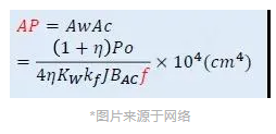
Optimize the size
• Design point 1: transformer high-frequency reduction small size
In a circuit board, you can see that the large volume is the transformer, so reduce the size of the transformer can save the size of the board. High frequency can reduce transformer size and transformer power transmission, so frequency from 200 KHZ ->300 KHZ ->500KHZ can reduce transformer volume.
• Design point 2: CCM operating mode reduces device size
• Design point 3: Original side feedback to reduce size
Increase Efficiency
EMC measures the interference caused by noise sources on sensitive devices, including conduction and radiation components. On the one hand, interference sources should be reduced and coupling paths should be optimized on the other hand.
In order to reduce EMI, the noise source in the circuit should be confirmed first. The noise source can be divided into conduction noise source and radiation noise source. The conducted noise source is generally the low frequency noise within 30MHZ, which is produced by the change of electric field. The conducting noise source is mainly that the switching action of power tube will lead to the mutation of MOS source-level voltage, which will cause the transformer to transfer the voltage mutation to the secondary side. Improving the driving resistance of MOS can reduce the switching speed, but the driving loss will increase. Or add absorption circuits to reduce high frequency oscillations. The stray parameters of transformer have a great influence on EMI, for example, transformer Cp (primary winding electric field) affects voltage spikes and current ripple.
The radiated noise source is the noise above 30M, which is the interference of the space magnetic field. It is composed of the high-frequency current loop. The high-frequency loop refers to the primary side loop and secondary side loop of the transformer.
Audited supplier
How to judge and deal with these abnormal phenomena in transformers?
55 Transformer Knowledge You Have to Know
Transformer No-load/Load Test Introduction
What is the main power transformer factory look like
Attending the MIDDLE EAST ELECTRICITY in March
China The Main Power Transformers manufacturers - Canwin
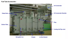
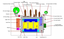
The Knowledge About Power Transformer-Oil Tank Part
The knowledge about "Power Transformer" is all here, Very Comprehensive, Collect it and Learn it!
What impact might the Russian-Ukrainian conflict have on the motor industry? Supplier