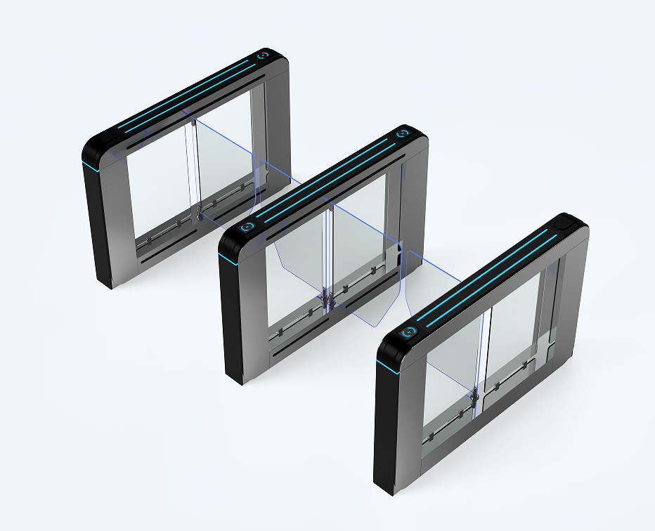
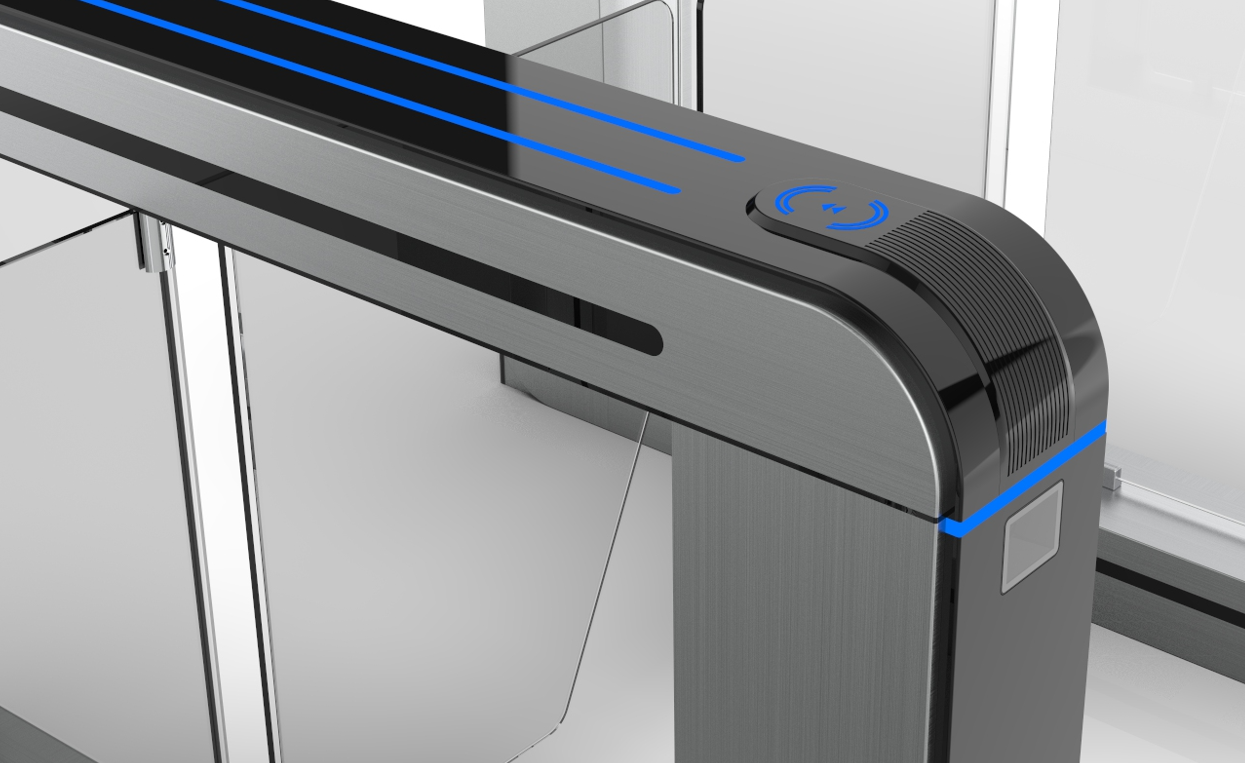
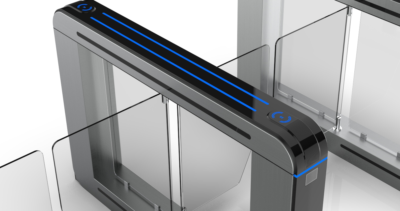
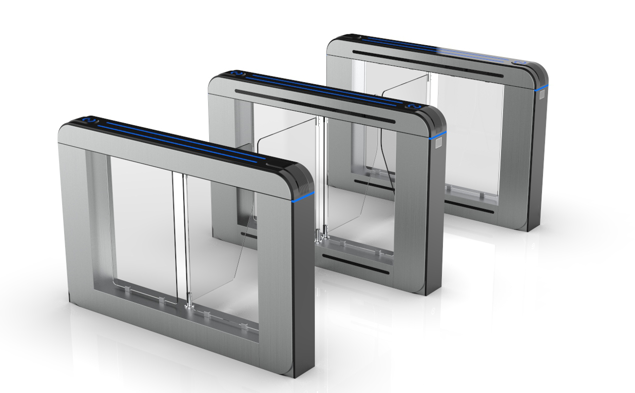
Karsun Access Luxury Swing Turnstile Gate
Swing turnstile is the intelligent access management produced by our company after several years R & D , this equipment organically integrate machinery electronics microprocessor control,and all kinds of different reading and writing equipment.Through figuring all kinds of different reading and writing equipment,and adopting reliable performance safety protection devices real-time alarm system, and direction indicator interface, realizing the access intelligent control and management by the mutual coordination.
 Audited supplier
1. Product Instruction
MBC2405C channel gate controller, equipped with brushless servo motor, servo control technology, real-time detection of motor position, no external encoder, self-learning load curve, with physical anti-clip protection, sensitivity adjustable characteristics;Support access mode Settings such as card swiping, free and prohibited;It has the logic detection of illegal entry, following passage, retention, reverse passage, infrared anti-clamp and so on. It is suitable for various kinds of channel gates, swing gates, wing gates, translation gates, three roller gate and so on.
1.1. Functional characteristics
MBC2405C brushless servo scheme | Ordinary brushless scheme | |
Adaptation motor | 2400 line position feedback brushless motor | Ordinary BRUShless DC motor |
The clip protection | Current + position dual detection, sensitivity adjustable | Low sensitivity without encoder to prevent clamping |
Control effect | Fast opening and closing speed, stable in place, no shaking | No position encoder in place stop instability |
1.2. Technical parameters
² Input power:DC24V,recommend a unilateral 150W / 6.5A;
² Adaptation motor:Brushless DC motor below 60W with 2400 line position feedback;;
² Communication mode: RS232 serial port communication, Modbus protocol is supported;
² Spare battery: DC12V (for switching off power);
² Working environment: -20℃ ~ 55℃, humidity below 90% (no condensation);
² Infrared sensor: 6 independent interfaces, PNP or NPN normally open, collector open type;
² Audio output: external 8w 4 Ω horn。
1.3. Normal open and fire protection functions
l Normally open mode:Long press the card button 3 seconds or the GND level 3 seconds of the swiping signal port, and the switch will enter the normal opening mode. At this time, the access door opens (infrared judgment fails), the light shows green light, and the buzzer and horn have no output. Cancel the signal, switch off the door, and restore the previous state.
Fire protection mode:Auxiliary port F is connected to GND, and the gate enters the fire-fighting mode. At this time, the door opens (infrared judgment fails), the light shows green light, the buzzer rings, and the voice announces "fire alarm, please evacuate quickly". Cancel the GND level, switch the gate and restore the previous
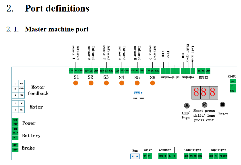
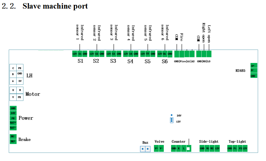
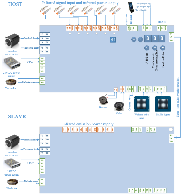
Interface of power supply, motor and encoder:
GND | External 24V switching power supply ,the power is recommended to be over 150W on one side | U |
Motor power line 4Pin jack
|
24V | V | ||
PE | W | ||
BAT- | External 12 v 1.3 Ah battery, without breaking function can not meet when power supply drop | PE | |
BAT+ | |||
GND | Used for external auxiliary incremental encoder | A |
Motor feedback 6Pin socket
|
A | B | ||
B | C | ||
Z | 5V | ||
5V | GND | ||
PE |
Input port:
12V | The infrared signal is connected to ports S1~S6. 3 groups of infrared layout can only connect S1 ~ S3, 4 groups of infrared layout can only connect S1 ~ S4, 6 groups of infrared layout can only connect S1 ~ S6. | GND | Signal common end |
S1~S6 | LO | The entrance direction opens the door for input signal | |
GND | RO | The exit direction opens the door for input signal | |
GND | Signal common end | A1 | |
Fire | Fire function input signal |
Output port:
BK+ | Directly connected with the clutch, there is no need to distinguish positive and negative | B+ | Connect active buzzer horn |
BK- | B- | ||
V+ | Voice horn, the recommended specifications: 8 w 4 Ω | L | GND is the common end of the counter; L is the count output of the inlet pass direction; R is the count output of the inlet pass direction; |
V- | R | ||
M | Alarm signal output, three rollers brake electromagnet output; 12V/24V output can be selected by jumper cap | GND | |
12V | Pass light/Top-light, which supports signal panel by default, P1 and P2 are respectively the green light control output ports of entrance and exit (high level). | 12V | Welcome light/side-light, which supports signal panel by default. W1 and W2 are respectively the green control output ports of the entrance and exit (high level). |
P1 | W1 | ||
P2 | W2 | ||
GND | GND |
Communication port:
TX | RS232 communication port, can communicate with the upper computer, pay attention to TX and RX connection need to cross | D+ | RS485 communication port as master and slave synchronous connection; The slave can only communicate with the host computer or the upper computer via RS485 |
RX | D- | ||
GND | GND |
1.3. Menu display
A- menu | |
Display code | function |
SE0 | Set zero point |
roP | Right opening |
CLo | close a door |
LoP | Zuokai |
rSt | reset |
1.4. Set the zero point(A-SE0)
Step 1: Exit to the main menu and find the parameter setting menu entry "A-", then press "■" on the right to enter the submenu, and press "▲" on the left to find "SE0"; Or enter "000" on the password entry screen.
Step 2: Again short press the right "■" confirm, the door into the disabled state, then put the door to the set position.
Step 3: After 5 seconds, the switch will reset automatically.
2. Quick debugging wizard
2.1. Express gate/swing gate/wing gate/translation gate:
step | name | operate | remarks |
1 | Set master-slave machine | Set F00 master 000, slave 001 Set the rotation direction of F01 motor to 0/1 | |
2 | Set gate type | Set F33 selection 0- swing gate double door 2- wing gate double door | The swing gate is set to 0, the wing gate and the translation door are set to 2; Power on again after setting. |
3 | Set motor reduction ratio | Set F49 parameters according to actual reduction ratio.
| The structure of the movement with speed reduction ratio needs to be set. |
4 | Set infrared type | Set infrared PNP/NPN jumper cap Set F37 0-PNP /1-NPN type | 0-PNP default value |
5 | Set infrared logarithm | Set F17 to select 3 pairs, 4 pairs or 6 pairs. | The default value is 1-6 for infrared |
6 | Set zero point | A-SE0 sets the zero position of door panel | Only the swing brake needs to be set to zero point. |
7 | Set the switch position | Set F14 and F15 parameters | F14 is reverse opening/closing. |
8 | Setting switch speed | Set F03 motor speed percentage |
3. Parameter list
Operation password
Password | Function | Password | Function |
211 | Debugging permission | 111 | Query infrared status |
618 | Reset | 321 | Restore the default value |
3.1. Parameter setting
NO. | Function code address | Function code name | default | Setting range | remarks |
F00 | 05 01 | Master-slave machine setting | 0 | 0 ~ 1 | 0- Master 1- Slave |
F01 | 00 0D | Rotation direction of motor | 0-0 | 0 ~ 1 | 0-0 (slave-master) 0- reverse 1- forward rotation |
F02 | 04 08 | reserve | 0 | 0 ~ 3 | reserve |
F03 | 09 00 | Switch speed (%) | 60 | 1 ~ 100 | Percentage of rated motor speed |
F04 | 09 01 | acceleration | 20 | 1 ~ 200 | The higher the value, the faster the acceleration. |
F05 | 09 06 | Running blocking current | 1.0 | 0 ~ 900 | 0 means no blocking judgment. The smaller the value, the higher the anti-pinch sensitivity. |
F06 | 09 08 | Looking for zero-turn blocking current | 2.5 | 1 ~ 100 | Increase appropriately when looking for zero abnormality. |
F07 | 09 09 | Velocity loop ratio | 120 | 1 ~ 999 | When the door panel is heavy, increase it appropriately. |
F08 | 09 0B | Position ring ratio | 45 | 1 ~ 999 | Appropriately reduce the overshoot in position. |
F09 | 08 1D | Push judgment angle strongly | 2.5 | 1 ~ 90.0 | The larger the setting value, the larger the pushing angle. |
F10 | 08 09 | Zero change speed | 10 | 1 ~ 80 | Percentage of rated motor speed |
F11 | 08 25 | Blocking mode selection | 1 | 1 ~ 2 | 1- rebound at an angle 2- Reduced speed and torque |
F12 | 08 18 | Push mode selection | 1 | 0 ~ 1 | 0- unlock clutch 1- lock clutch |
F13 | 08 10 | Emergency stop mode | 1 | 0 ~ 1 | 0- unlock clutch 1- lock clutch |
F14 | 0A 19 | Closed indentation angle | 5.0 | 1 ~ 90.0 | The smaller the setting value, the larger the opening and closing angle (corresponding to swing: reverse opening angle and wing brake: closing angle) |
F15 | 0A 1A | Open-in-place indentation angle | 5.0 | 1 ~ 90.0 | The smaller the setting value, the larger the opening angle (corresponding swing gate: positive opening angle, wing gate: opening angle) |
F16 | 0F 00 | Gate mode | 1 | 0 ~ 10 | 0: Aging mode 1. Two-way credit card swiping 2. Two-way freedom 3. Two-way prohibition 4: Forward swipe+Outbound freedom 5: Forward swipe card+Outbound prohibition 6: Forward freedom+outward swipe 7. Forward freedom+outward prohibition 8. Forward prohibition+outward freedom 9: Incoming prohibition+Outgoing credit card swiping 10: Test mode (no access logic) |
F17 | 0F 01 | Infrared logarithm | 1 | 0 ~ 2 | 0:3 to infrared 1:6 to infrared 2:4 to infrared |
F18 | 0F 02 | Continuous swipe card | 0 | 0 ~ 1 | 0: invalid 1: valid |
F19 | 0F 03 | Gate standby state | 0 | 0 ~ 1 | 0: normally closed 1: normally open |
F20 | 0F 04 | Maximum transit time | 10 | 1~ 65 | Unit: seconds, automatic closing after timeout. |
F21 | 0F 05 | In-channel swipe card | 1 | 0 ~ 1 | 0: disallowed 1: allowed |
F22 | 0F 06 | Is the door closed retrograde? | 1 | 0 ~ 3 | 0: Don't close the door 1: Close the door 2. Don't close the door after the reverse entry, and switch to the standby state after the passage is completed. 3. Turn back the door, and switch to the standby state after the back-up is cancelled. |
F23 | 0F 07 | Voice volume | 15 | 0 ~ 15 | |
F24 | 0F 08 | Trailing detection delay time | 30 | 0 ~ 999 | Unit: 10 ms |
F25 | 0F 09 | Do you lock the clutch when the door is in place? | 0 | 0 ~ 1 | 0: do not lock 1: lock |
F26 | 0F 0A | Whether illegal intrusion locks the clutch or not. | 0 | 0 ~ 1 | 0: do not lock 1: lock |
F27 | 0F 0B | Infrared filtering time | 1 | 0 ~ 500 | Unit: 10 ms |
F28 | 0F 0C | Allow the opposite credit card delay time after credit card swiping | 500 | 0 ~ 600 | Unit: 10 ms |
F29 | 0F 0D | Fire direction | 1 | 0 ~ 1 | 0: Open the door outward 1: Open the door inward |
F30 | 0F 0E | Post-swipe opening delay | 0 | 0 ~ 500 | Unit: 10 ms |
F31 | 0F 0F | Post-closing delay of traffic | 0 | 0 ~ 500 | Unit: 10 ms |
F32 | 0F 10 | Maximum residence time in channel | 10 | 0 ~ 999 | Unit: second |
F33 | 0F 12 | Type of controller (Power on again after modification) | 0 | 0 ~ 3 | 0: Swing double doors 1. Swing single door 2. Wing brake double doors 3. Wing brake single door |
F34 | 0F 14 | Trigger anti-pinch delay | 32 | 0 ~ 999 | Unit: 1ms |
F35 | 0F 15 | Exit anti-pinch delay | 250 | 0 ~ 999 | Unit: 1ms |
F36 | 0F 16 | Gate control command | 0 | 0 ~ 32 | 1: positive open 2: reverse open 16: forward normally open 32: reverse normally open (decimal unit) |
F37 | 0F 17 | Infrared type | 0 | 0 ~ 1 | 0:PNP normally open 1:NPN normally open |
F38 | 0F 18 | Open the door with or without buzzer. | 0 | 0 ~ 1 | 0: None 1: Yes |
F39 | 0F 19 | Chinese and English pronunciation | 0 | 0 ~ 1 | 0: Chinese 1: English |
F40 | 0F 1A | Entrance voice setting (welcome) | 0 | 0 ~ 79 | Define and query the Voice Content Table specifically. |
F41 | 0F 1B | Exit voice setting (bon voyage) | 6 | 0 ~ 79 | |
F42 | 0F 1C | Trailing voice setting (please pay attention to trailing traffic) | 3 | 0 ~ 79 | |
F43 | 0F 1D | Reverse voice setting (reverse entry, please exit and wait) | 2 | 0 ~ 79 | |
F44 | 0F 1E | Detention voice setting (do not stay as soon as possible) | 4 | 0 ~ 79 | |
F45 | 0F 28 | Gate breaking voice (illegal breaking, please verify and pass) | 1 | 0 ~ 79 | |
F46 | 0F 29 | RGB lamp output enable | 2 | 0 ~ 2 | 0: Disabled (traffic lights and welcome lights are valid) 1: bidirectional RGB lamp logic 2. Standard RGB lamp logic |
F47 | 05 04 | Baud rate setting (RS232) | 5 | 0 ~ 5 | 4800 / 9600 / 19200 / 38400 / 57600 / 115200 |
F48 | 08 14 | Blocking rebound angle | 20.0 | 0 ~ 99.9 | The higher the setting value, the larger the Big bounce angle. |
F49 | 08 00 | reduction ratio | 25 | 1 ~ 999 | Actual reduction ratio setting |
F50 | 0F 2A | Counter output mode | 0 | 0 ~ 1 | 0- Default counter output 1- output as traffic light 2- Output as welcome light |
F51 | 05 0D | Synchronization interface setting | 0 | 0~1 | 0-RS485 1-RS232 |
F52 | 09 03 | reserve | 60 | 1~100 | reserve |
F53 | 09 0C | reserve | 3.0 | 0~300 | reserve |
F54 | 08 0B | reserve | 15.0 | 1~90.0 | reserve |
F55 | 08 22 | reserve | 20 | 10~300 | reserve |
F56 | 0A 0C | reserve | 3 | 0~9 | reserve |
F57 | 0C 0C | reserve | 251 | 1~999 | reserve |
F58 | 06 07 | reserve | 100 | 0~ 900 | reserve |
F59 | 00 0E | reserve | 20 | 1~ 200 | reserve |
F60 | 0F 2F | Process triggered anti-pinch infrared selection | 1 | 0~ 1 | 0- Don't open the door (emergency stop) 1: Open the door |
F61 | 04 06 | Selection of motor model | 4 | 1~4 | 1:MBS59R-60S-2020 2:MBS80F-60A-3018 3:MBS57R-60A-2026 4:MBS70F-40A-1825 |
F62 | 0F 30 | Security check signal effective time setting | 5 | 0~65 | Unit: second |
F63 | 0F 34 | reserve | 0 | 0~90 | reserve |
F64 | 0F 35 | reserve | 0 | 0~90 | reserve |
F65 | 08 1F | Loose clutch time | 200 | 0~900 | Unit 0.1ms |
Audited supplier
Karsun Access Patent New Flap Turnstile
Karsun Access Patent Luxury Swing Turnstile access control
Karsun Access Patent high speed gate pedestrian access control rfid turnstile gate
Security pedestrian access control high speed gate turnstile with RFID, IC Card, Id card reader KARSUN
New Model Flap Turnstile Access Control Use for Office Building Entrance Karsun
Karsun Access Luxury Swing Turnstile Gate
Biometric Face Recognition With Thermal Temperature Hand Sanitizer Attendance Face Scanner Access Control
Face Recognition Access Control Outdoor Face Recognition Camera SDK Time Attendance IC Card Reader Access Control System
Touch Screen Wifi AI Face Recognition Temperature Detection Biometric Fingerprint Clock Access Control


