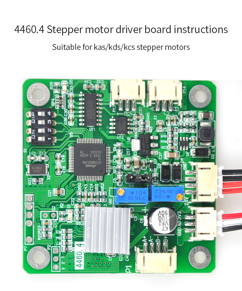
Kamoer Stepper motor peristaltic pump 4460.4 driver board
Stepper motor drivers are specifically designed to drive stepper motors, which are capable of continuous rotation with precise position control, even without a feedback system.
Our stepper motor drivers offer adjustable current control and multiple step resolutions, and they feature built-in translators that allow a stepper motor to be controlled with simple step and direction inputs.
 Audited supplier
4460.4 Stepper motor driver board Instructions for use
Can connect with KAS, KCS, KDS etc. stepper motor
I、Circuit board features introduced
4460.4 stepper motor driver board can be four kinds of ways to control the stepper motor speed:
1. External Interface potentiometer P4 (the default)
2. Built-in potentiometer VR1 (settable)
3. RS232 communication bus speed (P13)
4. RS485 communication bus speed (P14)
S1: P4 potentiometer or speed control potentiometer knob VR1 function selection set or mailing address;
P13: RS232 interface (PH-3Y connector);
P14: RS485 Interface (PH-3Y connector);
P10: Power input interface (input voltage range DC12 ~ 24V, XH-4Y connector);
P4: External speed potentiometer Interface (PH-3Y connector);
P1: Peristaltic pump stepper motor interface (XH-4Y connector);
P3: Knob to select the speed control circuit internally or externally, as an external speed (P3 2, 3 jumper cap short);
VR1: Built-in potentiometer speed (potentiometer built elected governor when), clockwise to increase;
VR2: Stepper motor current adjustment potentiometer;
P2: Stepper motor stops used decay mode (default brake mixed-decay modes);
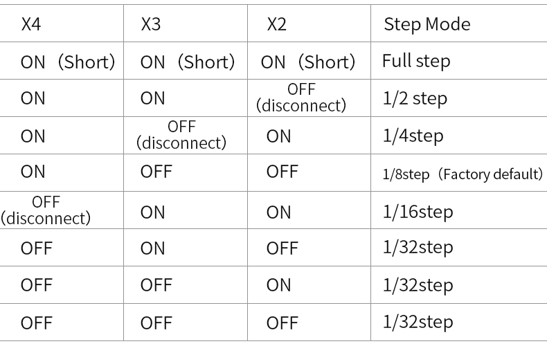
X2, X3, X4: Set segment (back of the board, the default segmentation 8) (Figure 1.3)
Note 1: 4460.3 driver board can connect with KAS, KCS, KDS etc. stepper motor driven peristaltic pump. The following descriptions as an example of KAS, same for KCS, KDS control methods, only connected to 4460.3 motor interface of the corresponding stepper motor pump.
II、External speed control knob (default connection)
A) DIP switch settings
When using speed dial, you need to put all the DIP switch to "ON" position (Figure2.1)
B) short circuit function selection jump cap
When using an external knob control, you need to select P3 connected to 2, 3 short
hop cap
C) Connect speed control knob P4
D) Connect KAS peristaltic pump P1
E) Connect the power cord P10
F) Connect the power; clockwise adjusting VR1 knob, the speed increases
*Note: When the knob is used for speed control, it is not necessary to connect the communication line
III、Built-Speed knob VR1
A) DIP switch settings
When using speed dial, you need to put all the DIP switch to "ON" position (Figure 2.1).
B) Short circuit function select jump cap
When using the built-in potentiometer speed control knob, you need to select P3
connected to 2, 3 short hop cap
C) Connect the KAS peristaltic pump to P1
D) Connect the power cord P10
*Note: External speed potentiometer P4 without connecting
IV、RS232, RS485 control speed, running
A) Setting the DIP switch (see Figure 2.2)
When RS232, RS485 control when you need to set the mailing address of 4460.3 driver ;
4 DIP switch BCD code corresponding to the four, 1-bit DIP switch for the highest bit, 4-bit DIP switch is the lowest bit.
DIP address: 0x00-0x0E correspond mailing address 0xC0-0xCE;
*Note: All dial to "ON", the knob for speed control function selection, 0xCF address is not available for the mailing address.
B)Connected to the communication line
a、When you need to use RS232 communication, plug the communication cable into the RS232 communication port P13; when you need to use RS485 communication, plug the communication cable into the RS485 communication port P14.
b、RS232 port definition: The terminal next to GND TX RX is corresponding to the definition of RS232 GND TXD RXD;RS485 port definition: The terminal next to the B G A is corresponding to the definition of RS485 B (D-) GND A (D +);
C)Connect the KAS peristaltic pump to P1
D)Connect the power cord P10
E)Connect the power,send commands to control operation of the pump.
V、The current regulation (factory-adjusted)
A) Current regulator (current range 0 ~ 2A)
VR2: stepper motor current regulator potentiometer: clockwise to adjust the current increases, the motor torque is increased.
Generally in the case of easy motor out of step, increase the current (the proposed
current as small as possible, the large current , the more heating of motor).
Audited supplier
Kamoer KFS Micro Peristaltic Dosing Pump 24V With Stepper Motor For Hotsale Electric Aquarium
Kamoer KMPP Peristaltic Mini water pump(1.8ML/MIN)
Kamoer KCM-ODM High Precision Small Peristaltic Dosing Pump 12V /24V with Stepper Motor-Installation ODMA Type
Kamoer 420ml/min KCM 12V /24V Mini Peristaltic Water Pump With Stepper Motor And BPT/Silicon Tube Peristaltic pump filli
Kamoer KCS3 Threaded Joint Stepper Motor Peristaltic Pump 24V Electric Water Pump(S/BPT Tube) 300ml/min Max Flow Rate
Kamoer KHS 12V/24V Mini Peristaltic Water Pump with DC/BLDC Motor
Kamoer KHM Peristaltic Pump High-precision BLDC Motor with Plastic Gear Drive (Norprene tunbe or silicone tube)
Kamoer KAS 12V/24V Peristaltic Pump with 42 Stepper Motor, 3 or 6 Rotors and Silicone Tube or BPT Tube for Selection
Kamoer F01A STP Peristaltic Metering Pump Machine With 24V Power Adapter Stepper Motor Dosing Pump for Aquarium


