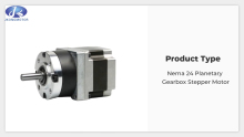
JK3DM683 Nema 23 / 24 1.2Degre 3 Phase Stepper Motor Driver
Product Type: Nema 23 / 24 1.2Degree 3 Phase Stepper Motor Driver
Feature summary:Low heat generation, low motor vibration and stable operation, Smooth operation and low noise
Place of Origin:china
Minimum order quantity:10pcs
Support Motor: Nema23 or Nema 24 3 Phase Stepper Motor
Packing:The sample is packed in carton,the batch with plastic pallet
Delivery time:Standard product: 7-10days
Customized product: 25-30days
transaction mode:EXW, FOB, FCA, CIF, FAS, CFR, CPT, CIP, DAF, DEQ, DDU, DDP...
 Audited supplier
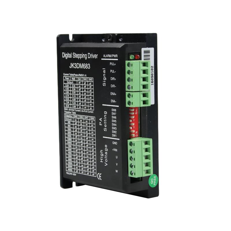
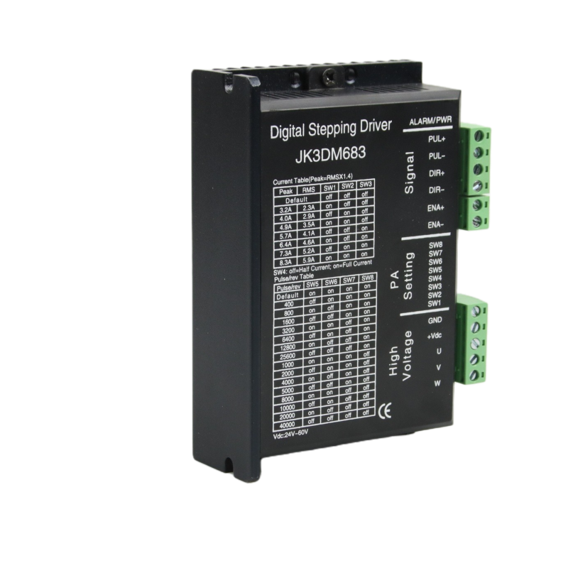
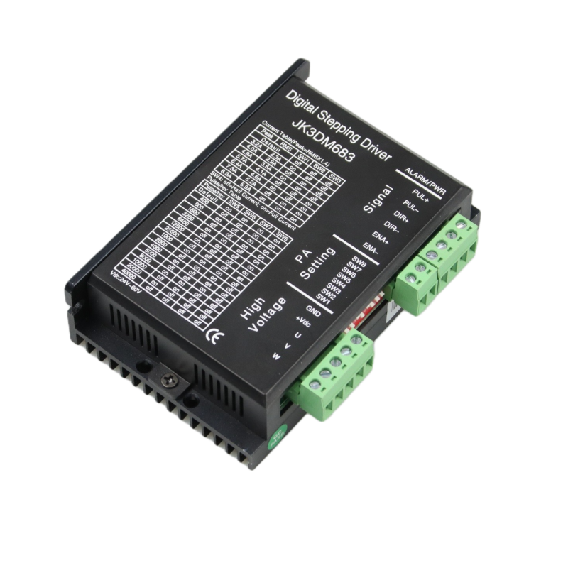
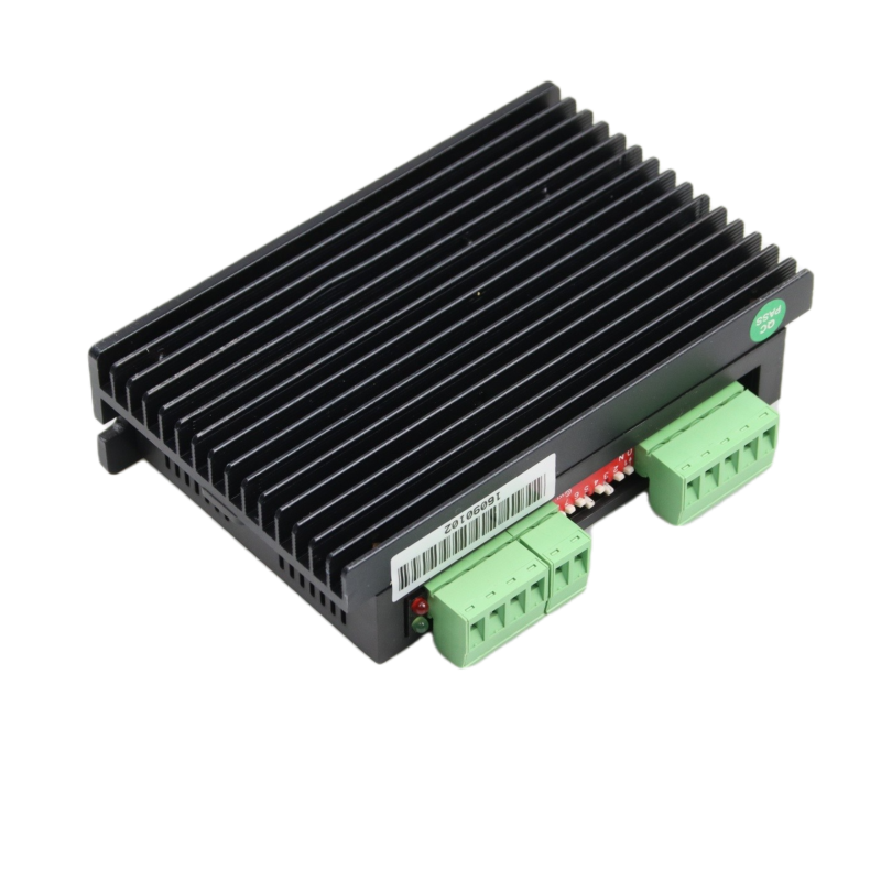
The JK3DM683 is a new generation high-performance digital stepper driver based on DSP with advanced control algorithm. The motors driven by JK3DM683 can run with much smaller noise and much less vibration than other drivers in the market. The JK3DM683 possess the feature of lower noise, lower vibration, and lower heating. The JK3DM683’s voltage is DC 24V-60V. It is suitable for all the 3-phase hybrid stepper motor whose current is less than 5.6A.There are 16 kinds of microstep of 3DM683. The maximum step number of JK3DM683 is 51200 steps/rev (microstep is 1/256 ). Its current range is 3.2A-8.3A, and its output current has 8 stalls. JK3DM683 has automatic semi-flow, over-voltage, under voltage and over-current protection function.
Peak | RMS | SW1 | SW2 | SW3 |
Default | OFF | OFF | OFF | |
3.2A | 2.3A | ON | OFF | OFF |
4.0A | 2.9A | OFF | ON | OFF |
4.9A | 3.5A | ON | ON | OFF |
5.7A | 4.1A | OFF | OFF | ON |
6.4A | 4.6A | ON | OFF | ON |
7.3A | 5.2A | OFF | ON | ON |
8.3A | 5.9A | ON | ON | ON |
MICROSTEP SELECTION
Pulse/Rev | SW5 | SW6 | SW7 | SW8 |
Default | ON | ON | ON | ON |
800 | OFF | ON | ON | ON |
1600 | ON | OFF | ON | ON |
3200 | OFF | OFF | ON | ON |
6400 | ON | ON | OFF | ON |
12800 | OFF | ON | OFF | ON |
25600 | ON | OFF | OFF | ON |
51200 | OFF | OFF | OFF | ON |
1000 | ON | ON | ON | OFF |
2000 | OFF | ON | ON | OFF |
4000 | ON | OFF | ON | OFF |
5000 | OFF | OFF | ON | OFF |
8000 | ON | ON | OFF | OFF |
10000 | OF | ON | OFF | OFF |
20000 | ON | OFF | OFF | OFF |
40000 | OFF | OFF | OFF | OFF |
Default: The pulse can be customized according to customers’ requirements.
Phenomenon | Reason | Solution |
The red indicator is on. | 1. A short circuit of motor wires. | Inspect or change wires |
| 2. The external voltage is over or low than the driver’s working voltage. | Adjust the voltage to a reasonable rang |
| 3. Unknown reason | Return the goods |
It can be applied in a variety of small scale automation equipment and instruments, such as labeling machine, cutting machine, packing machine, drawing machine, engraving machine, CNC machine and so on. It always performs well when it is used in equipment which requires for low-vibration, low-noise, high-precision and high-velocity.
Driver function | Operating instructions |
Output | Users can set the driver output current by SW1-SW3 three switches. |
Microstep setting | Users can set the driver Microstep by the SW5-SW8 four switches. The setting of the specific Microstep subdivision, please refer to the instructions of the driver panel figure. |
Automatic half | Users can set the driver half flow function by SW4. "OFF" indicates the quiescent current is set to half of the dynamic current, that is to say, 0.5 seconds after the cessation of the pulse, current reduce to about half automatically. "ON" indicates the quiescent current and the dynamic current are the same. User can set SW4 to "OFF", in order to reduce motor and driver heating and improve reliability. |
Signal interfaces | PUL+ and PUL- are the positive and negative side of control pulse signal; DIR+ and DIR- are the positive and negative side of direction signal; ENA+ and ENA- are the positive and negative side of enable signal. |
Motor interfaces | A+ and A- are connected to a phase winding of motor; B+ and B- are connected to another phase winding of motor. If you need to backward, one of the phase windings can be reversed. |
Power interfaces | It uses DC power supply. Recommended operating voltage is 24VDC-60VDC, and power consumption should be greater than 100W. |
Indicator lights | There are two indicator lights. Power indicator is green. When the driver power on, the green light will always be lit. Fault indicator is red, when there is over-voltage or over-current fault, the red light will always be lit; after the driver fault is cleared, if re-power the red light will be off. |
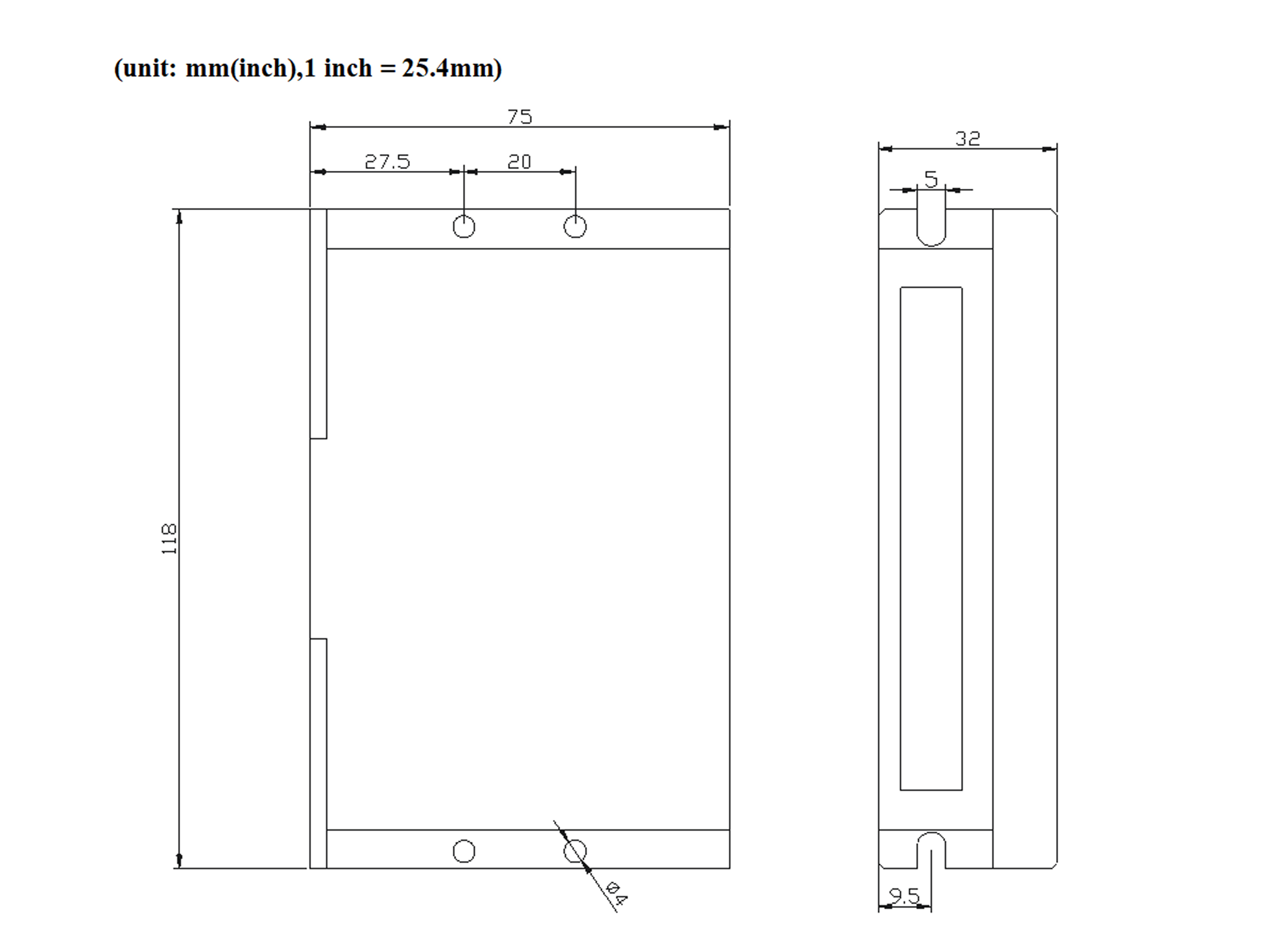
Installation | Driver dimensions:118×75×32mm, please refer to dimensions diagram. Please leave 10CM space for heat dissipation. During installation, it should be close to the metal cabinet for heat dissipation. |
Product Dimension
1、Q: Are you factory?
A:Yes, we are factory, and we produce stepper motor/driver, Servo motor/driver, BLDC motor/driver...
2、Q: How to select models?
A:Before purchasing, please contact us to confirm model No. and specifications to avoid any misunderstanding.
3、Q: How do you ship the goods?
A: Sea and by air, also accept customer appointed.
4、Q: Can I test sample?
A: Yes, sample charged can be offered for testing.
5、Q: Can we be agent or distributor?
A: Yes, welcome and we will support you.
6、Q: Can you do OEM or ODM service?
A: Yes, we have R&D department and accept OEM and ODM service.
Audited supplier
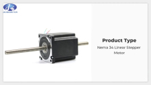
1.8°Nema 34 Linear Stepper Motor 86x86mm for for 3D printer CNC Engraving Milling Machine
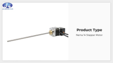
1.8° Nema 14 Hybrid Stepper Motor 35x35mm 0.5A or 1A with 4leads
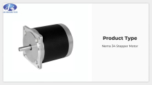
1.8° Nema 34 Hybrid Stepper Motor 86x86mm with 4leads or 6leads
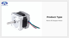
1.8° Nema 16 Hybrid Stepper Motor 39x39mm with 4leads or 6leads
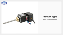
1.8 Degree Nema 11 Hybrid Stepper Motor 28x28mm 0.67A or 0.95A With 4leads or 6leads
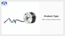
0.9° 36mm 2-Phase Hybrid Round Stepper Motor 36x36mm With 4leads
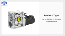
1.8° Nema 24 Worm Gearbox Stepper Motor 60x60mm for CNC Milling
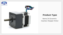
1.8° Nema 24 HSG Eccentric Gearbox Stepper Motor 60x60mm for CNC Milling
1.8° Nema 24 HSP Planetary Gearbox Stepper Motor 60x60mm for CNC Milling