BRJ-1000
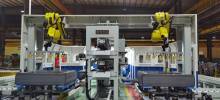
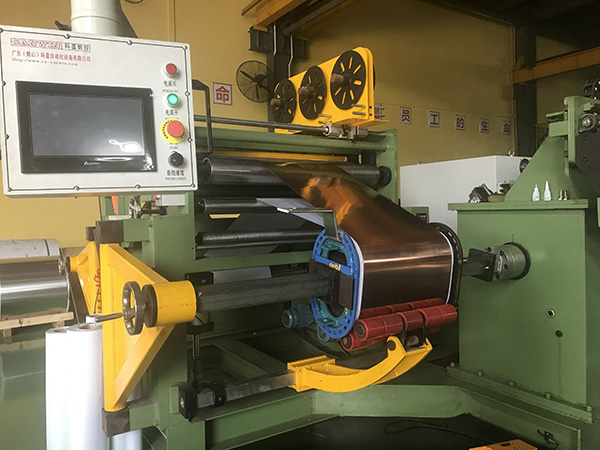
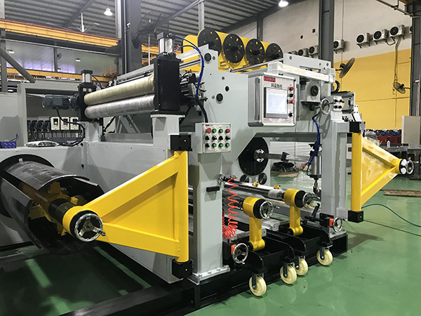
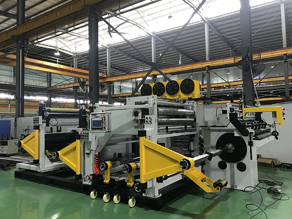
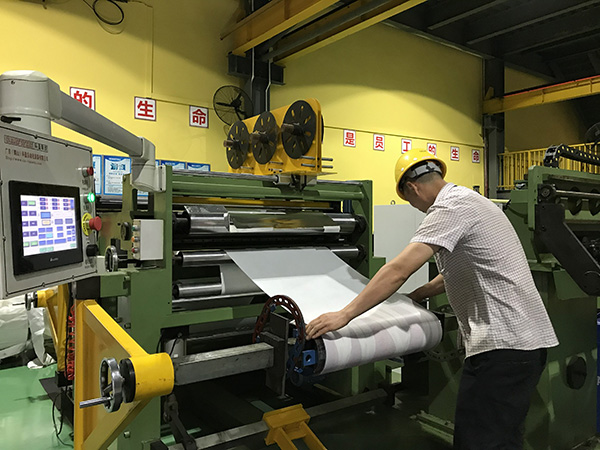
This foil winding machine has unique appearance, convenient operation, intuitive data display, high degree of automation, and is well received by users. This foil winding machine is widely used in oil-immersed transformer, dry transformer, special transformer and reactor production required.
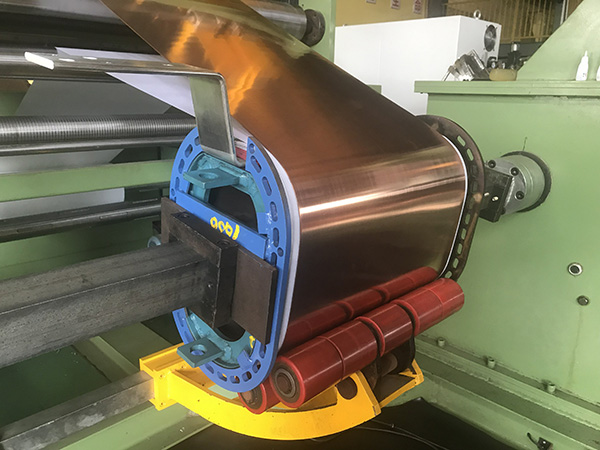
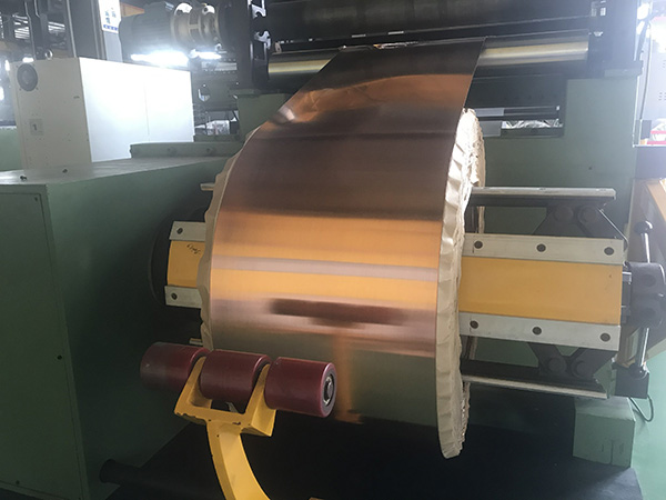
Foil coils are of different thicknesses copper or aluminum foil as a conductor, with wide ribbon insulation material as the insulation between layers, with narrow ribbon insulation material as the end insulation, completed winding one time, forming a coil. The inner and outer leads of the coil are welded and wrapped up at the same time.
 Audited supplier
2.1 Standard main parameter table (can be customized)
| No. | Item | Parameter |
| BRJ-1000 | ||
| 1 | Coil working range | |
| 1-1 | Axial length | 500-1100mm |
| 1-2 | Axial length (with guide line) | 650-1300mm |
| 1-3 | ID (Excluding row) | Diameter ¢100 |
| 1-4 | OD MAX | Diameter ¢1200 |
| 1-5 | ID MIN | Diameter ¢200 |
| 1-6 | Suitable coil shape | Circle \ rectangle |
| 2 | Coil material | |
| 2-1 | Material | Copper foil \ Aluminum foil |
| 2-2 | Width | 200-1050mm |
| 2-3 | Thickness | Copper foil: 0.3-2.5mm |
| Aluminum foil: 0.5-3mm | ||
| 3 | Decoiler | |
| 3-1 | Coil ID | Diameter ¢400\510 |
| 3-2 | Coil OD | Diameter ¢1000 |
| 3-3 | Coil shaft length | 1000mm |
| 3-4 | Core shaft size | Diameter ¢400-520 |
| 3-5 | Loading weight | 2000kg |
| 3-6 | Tension | 20000 N |
| 3-7 | Working pressure | 0-0.6(MP) |
| 4 | Coiler | |
| 4-1 | Output torque | 6544Nm |
| 4-2 | Wind power | Double layer 15KW |
| 4-3 | Speed adjustment mode | Frequency stepless governor |
| 4-4 | Winding speed | 0-25(r/min) |
| 5-1 | Weld way | Argon arc welding TIG |
| 5-2 | Welding speed | 0-25(r/min) |
| 6-1 | Shearing way | Electric rolling shear |
| 6-2 | Shear speed | 0.42m/min |
| 7 | Insulating layer | Two sets |
| 7-1 | Air shaf OD and ID | Apply to the coil ID Ф75.5~Ф78 |
| 8 | End insulation device | 6 set (can customized) |
| 8-1 | QTY | |
| 8-2 | ID | 44MM |
| 8-3 | OD | ¢350MM |
| 8-4 | Width | 15-50MM |
| 9 | Counting precision | 0.1 turns |
| 10 | Deviation correction mode and accuracy | Photoelectric correction ±0.5mm |
2.2 The composition and function of the equipment
(1. Decoiler) (2. Feeding device) (3. Expanding device) (4. Compression device, Dust removal device) (5. Shearing device) (6. End insulation uncoiling device) (7. Winding machine) (8. Welding device) (9. Layer insulation uncoiling device) (10. Deviation rectifying device) (11. Electrical control device).
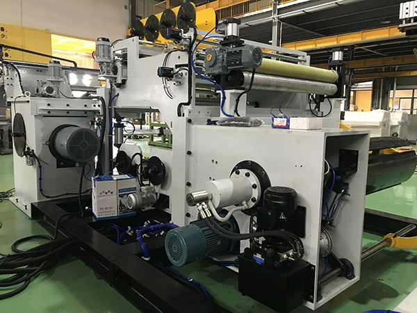
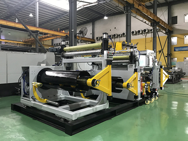
Decoiler is not only support the coil and feeding, but also has automatic deviation adjustment function.The main shaft of the uncoiling machine has a section of square section, and three sets of inclined hair blocks support three arc-shaped expansion blocks, which can tighten the coil material on the material barrel.The main shaft can be actively operated in forward or reverse direction for uncoiling, discharging and receiving, so as to adjust the working condition at any time. In linkage, the main shaft is disengaged from the driving device through the clutch.The main shaft is equipped with two sets of pneumatic controller damping devices, which can be used independently or in parallel, making the adjustment range of expansion force wide.The power of damping device is pneumatic, easy to control, clean and safe.The whole uncoiling mechanism is connected with the main frame by linear guide rail with large specifications, and equipped with servo power system. According to the instructions of the PLC main control system, the uncoiling mechanism will move around the guide rail quickly and accurately, so as to ensure that the foil is always in the accurate position according to the feedback of the deviation detection signal and realize the deviation adjustment function of the foil belt.
The case of the winding machine is composed of thick steel sheet, which is machined after the stress elimination treatment by annealing. The gear of transmission mechanism and reducer are made of large modulus, helical tooth shape and hard tooth surface parameters. It guarantees the mechanical strength of large torque output and the smooth operation of the whole equipment with very low working noise.
Adopt frequency conversion speed regulation mode, provide maximum torque and suitable speed at low speed. High speed provides the right torque, maximum speed. To meet different winding process requirements.When winding the spindle, the slope of acceleration of starting and stopping is set reasonably, and the braking function is configured to improve the operation of the equipment. High power automatic brake motor, abundant reserve power.
After winding, cut the foil strip.The cutting mouth must be flat so that can weld well with the lead, especially the butt welding between foil belt. BRJ foil winding machine adopts rolling shear way to cut the foil belt. The upper pressure knife is mounted on a swinging rotary frame with a cylinder on each side of the lower end of the rotary frame to press the upper pressure knife and foil belt on the base. The lower hob is mounted on the sliding frame, and driven by the motor and screw rod to run on the linear guide rail, so that the lower hob rolls along the upper edge of the pressing edge, and the foil belt can be cut.In order to adjust the edge position of the upper press knife, the turning point of the rotary frame can be moved back and forth.In order to make the lower hob and the upper hob close but not bite the knife, the lower hob can move axial, through the spring press up the edge, reduce the difficulty of the assembly between the hob slider and the base, improve the shearing accuracy.
The welding way is argon arc welding (TIG) with AC and DC conversion, no filler.
Each branch pressure, flow independently adjustable.The implementation of each pneumatic action is controlled by PLC implementation program, and the pneumatic pipeline layout is reasonable and reliable.
| 1 | HIG | DELTA |
| 2 | Transducer | DELTA |
| 3 | Correcting deviation system | KPS-C2 |
| 4 | PLC program controller | DELTA |
| 5 | Electric elements | Schneider/ Omron |
| 6 | Pneumatic components | AirTAC |
| 7 | Linear guideway | HIWIN |
Audited supplier
How to judge and deal with these abnormal phenomena in transformers?
55 Transformer Knowledge You Have to Know
Transformer No-load/Load Test Introduction
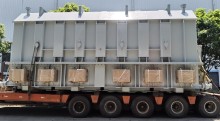
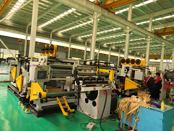
What is the main power transformer factory look like
Attending the MIDDLE EAST ELECTRICITY in March
China The Main Power Transformers manufacturers - Canwin
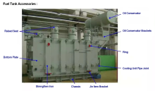
The Knowledge About Power Transformer-Oil Tank Part
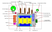
The knowledge about "Power Transformer" is all here, Very Comprehensive, Collect it and Learn it!
What impact might the Russian-Ukrainian conflict have on the motor industry? Supplier